
TM 9-1240-400-34&P
4
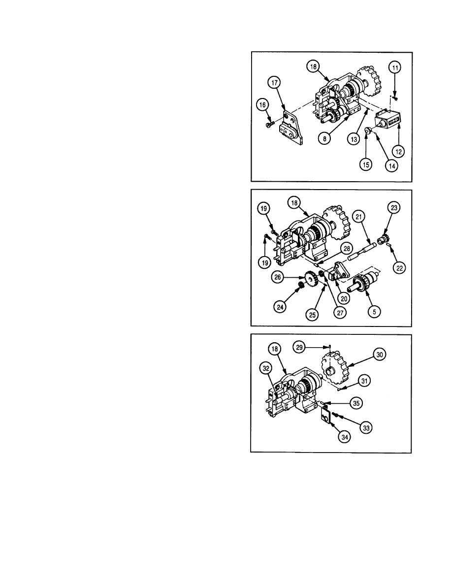
Remove four screws (11) and rotating counter (12)
from base assembly (8).
5
Remove two pins (13) only if damaged.
6
Remove tapered pin (14) and gear (15) from rotating
counter (12).
7
Remove two screws (16) and adapter (17) from base
(18).
8
Remove two screws (19) and bracket (20) from base
(18) with differential assembly (5) and pivot (21)
attached.
9
Remove differential assembly (5) from bracket (20).
10 Remove tapered pin (22) and spur gear (23) from
pivot (21).
11 Remove pivot (21) from bracket (20).
12 Remove retaining ring (24), tapered pin (25), spur
gear (26), and retaining ring (27) from pivot (21).
13 Remove two pins (28) only if damaged.
14 Remove tapered pin (29), knob assembly (30),
and key (31) from pivot (32).
15 Remove two screws (33) and bracket (34) from
base (18).
16 Remove pin (35) only if damaged.
5-47
