TM 9-1240-382-34
2-5 DAYLIGHT BODY ASSEMBLY - CONTINUED
LOCATION
ITEM
REMARKS
ACTION
INSTALLATION/ADJUSTMENT
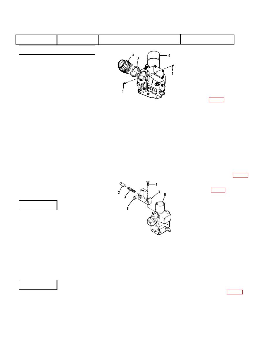
Thread the retainer ring (1) onto
the eyepiece assembly (2).
Screw the eyepiece assembly (2)
Daylight
Eyepiece
into the body assembly (3) only
Body
Assembly
enough to ensure that it will not
Assembly
fall off. Set the diopter ring (4) in
the center of its travel. While
viewing a target at minimum of
600 meters away, use a
dioptometer (p 1-3) set at zero,
and screw the eyepiece assembly
(2) into the body assembly
(3)until the target is clear. Lock
the eyepiece assembly (2) in
position with locking ring (1).
While holding the eyepiece
assembly to prevent movement,
loosen setscrews (8) and set the
Retainer Ring (1)
index arrow toward the objective
Eyepiece Assembly (2)
of the daylight body and tighten
Body Assembly (3)
setscrews (8).
Loosen set
Diopter Ring (4)
screws (6) and set diopter scale
Diopter Scale (5)
(5) on zero and tighten setscrews
Setscrew (6)
(6). Tighten the retainer ring (1)
Index (7)
using a spanner wrench (App. D.
Setscrew (8)
Fig.D2). Remove the setscrew
Setscrew (9)
(9) and inject sealing compound
MIL-S-11030 (App B) through the
setscrew hole. Reinstall the
setscrew (9).
REMOVAL
Remove retaining ring (1) from
the groove in plunger (2) while
Daylight
Front Alinement
pressing the blade of
a
Body
Key
screwdriver against the plunger to
Assembly
relieve spring pressure. Remove
the plunger (2) and spring (3).
Retaining Ring (1)
Remove screws (4) and remove
Plunger (2)
the alinement key (5) from the
Spring (3)
body assembly (6).
Screw (4)
Key (5)
Body Assembly (6)
WARNING
Care must be exercised in
removing
plunger
(2)
which is under spring
CLEANING
Clean all components in
pressure.
solvent P-D-680 (App B)
Daylight
Front Alinement
and dry thoroughtly.
Body
Key
Assembly
2-22


