TM 9-1240-382-34
LOCATION
ITEM
REMARKS
ACTION
INSPECTION/REPAIR
Check
all
parts
for
Front Alinement
Check
Body
Key
screws
for
worn
or
Assembly
damaged threads. Check
spring for resiliency. Repair
INSTALLATION
is limited to replacement of
missing,
defective,
or
Front Alinement
damaged parts.
Body
Key
Assembly
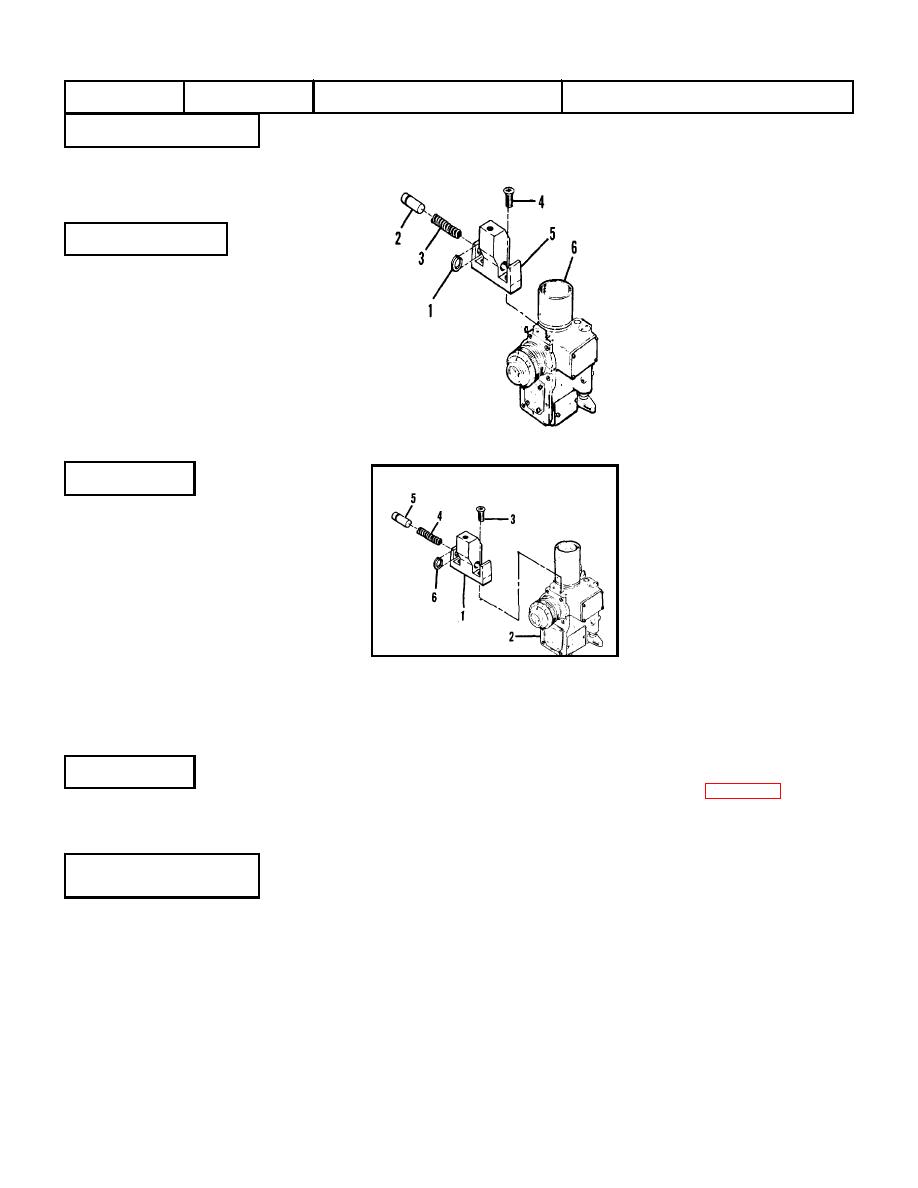
Secure alinement key (1)
to body assembly (2) with
Key (1)
two
screws
(3).Install
Body Assembly (2)
spring (4). Insert plunger
Screw (3)
(5) halfway into key (1) and
Spring (4)
install snap ring (6) on
Plunger (5)
plunger
(5).
Depress
Retaining Ring (6)
plunger and slide snap ring
into groove on plunger.
REMOVAL
Remove retaining ring (1)
from the groove in plunger
Rear Alinement
(2) while pressing the
Body
Key and Block
blade of a screwdriver
Assembly
against the plunger to
relieve spring pressure.
Remove the plunger (2)
Retaining Ring (1)
and spring (3). Remove
Plunger (2)
screws (4) and remove the
Spring (3)
alinement key (5) from the
Screw (4)
body
assembly
(6).
Key (5)
Remove two screws (7),
Body Assembly (6)
lockwashers (8) and block
Screw (7)
(9). Repair is limited to
WARNING
Lockwasher (8)
replacement of missing,
Care must be exercised in
Block (9)
defective, or damaged
removing plunger (2) which
parts.
Clean
all
is under spring pressure.
CLEANING
components in Solvent P-
D-680 (App B) and dry
Rear Alinement
thoroughly.
Body
Key and Block
Assembly
Check
all
parts
for
INSPECTION/REPAIR
Check
screws
for
worn
or
Rear Alinement
damaged threads. Check
Body
Key and Block
spring for resiliency. Repair
Assembly
is limited to replacement of
missing,
defective,
or
damaged parts.
2-23


