
ARMY TM 9-1240-379-34
MARINE CORPS TM 04332A-34
3-4. OPTICAL CELL ASSEMBLYMAINTENANCE INSTRUCTIONS. (cont)
lNSPECTION/CLEANING/REPAIR
1 Clean optical surfaces in accordance
w i t h TM 9-254.
2 Replace any damaged, broken, or miss-
ing parts. See TM 9-1240-379-34P.
I
REASSEMBLY
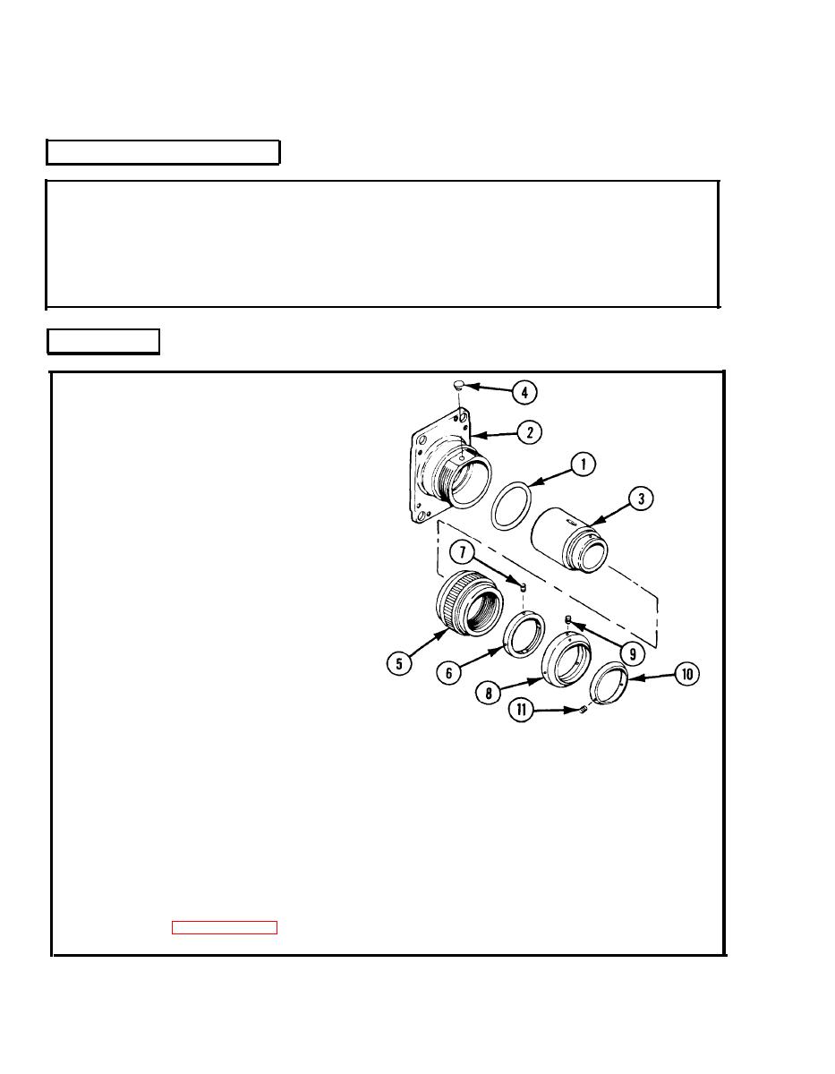
1 Apply a light coat of grease to new
preformed packing (1) and install in ring
groove inside adapter (2).
2 Install optical element cell (3) on adapter
(2), alining slot in optical element cell
with stop hole in adapter.
3 Install stop (4) in adapter (2).
4 Install optical retaining ring (5) on
adapter (2) and turn optical retaining ring
clockwise until it seats against adapter.
Do not tighten.
5 Install round plain nut (6) on optical re-
taining ring (5) and hand tighten.
CAUTION
Make sure that setscrew
securing round plain nut is
9 Apply sealing compound to three
below outside surface of round
setscrews (9) and install in diopter scale
plain nut to prevent damage to
diopter scale.
(8); tighten setscrews.
10 Install dial pointer (10).
6 Apply sealing compound to threads of
setscrew (7) and install in round plain nut
11 Apply sealing compound to two
(6). Tighten setscrew.
setscrews (11) and install in dial pointer
7 Install diopter scale (8) on optical ele-
(10); tighten setscrews.
ment cell (3).
12 After maintenance has been completed,
purge and charge in accordance with
8 Adjust diopter scale (8) according to in-
T M 750-116.
structions in paragraph 3-10c(2).
