TM 9-1240-382-34
LOCATION
ITEM
REMARKS
ACTION
INSPECTION - Continued
Rotate the RETICLE
switch (8)
clockwise from OFF and LO to HI.
The image of the reticle should
Periscope
Elbow
appear as you look into the eyepiece
Assembly
(6) of the elbow assembly (1). The
image should grow brighter as you
rotate the switch (8) towards HI; it
should become dimmer as you
return the RETICLE switch (8) to LO,
and should disappear when you turn
the RETICLE switch (8) to OFF.
Move the shutter switch (5) to OFF.
If reticle fails to operate, refer to
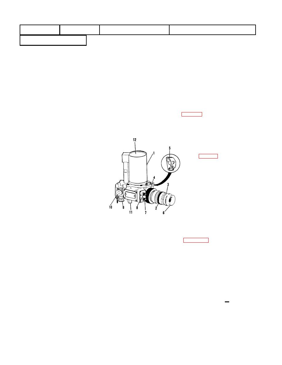
Elbow Assembly (1)
Diopter Ring (2)
The boresight knobs (9 and 10) will
Diopter Scale (3)
be rotated through their full range of
Focus Ring (4)
travel without binding and shall
Shutter Control
engage the metallic stops at each
Switch (5)
end of travel. If knobs fail to perform
Eyepiece (6)
refer to page 2-2.
Tube Control
Switch (7)
Utilize the M30 instrument light to
Reticle Control
energize the emergency power
Switch (8)
receptacle (11). Cover the entrance
Elevation
window (12) with a dark cloth
Boresight Knob (9)
allowing only a small amount of light
Deflection Boresight
in. Move the shutter switch (5) to the
Knob (10)
ON position. Rotate the TUBE and
Emergency Power
RETICLE switches (7 and 8) until an
Receptacle ( 11)
image and phosphor grain appears.
Entrance
Turn the RETICLE switch (8) and
Window (12)
shutter switch (5) to OFF and the
TUBE switch (7) to LO. Remove the
M30 instrument light. If tube and
CAUTION
reticle fail to operate check diode
Do not leave the RETICLE
receptacle (11). If either fails to
switch at a high setting or the
operate now return to depot for
image intensifier tube will be
repair.
damaged.
NOTE
CAUTION
24 Volt power shall be shut off to
A power supply with applicable
determine operability of the
leads may be utilized in lieu of the
emergency power receptacle
M30 instrument light. DC voltage
(11).
to be applied to receptacle (11)
shall be 3 volts DC + 0.3 volt.
3-3


