TM 9-1240-382-34
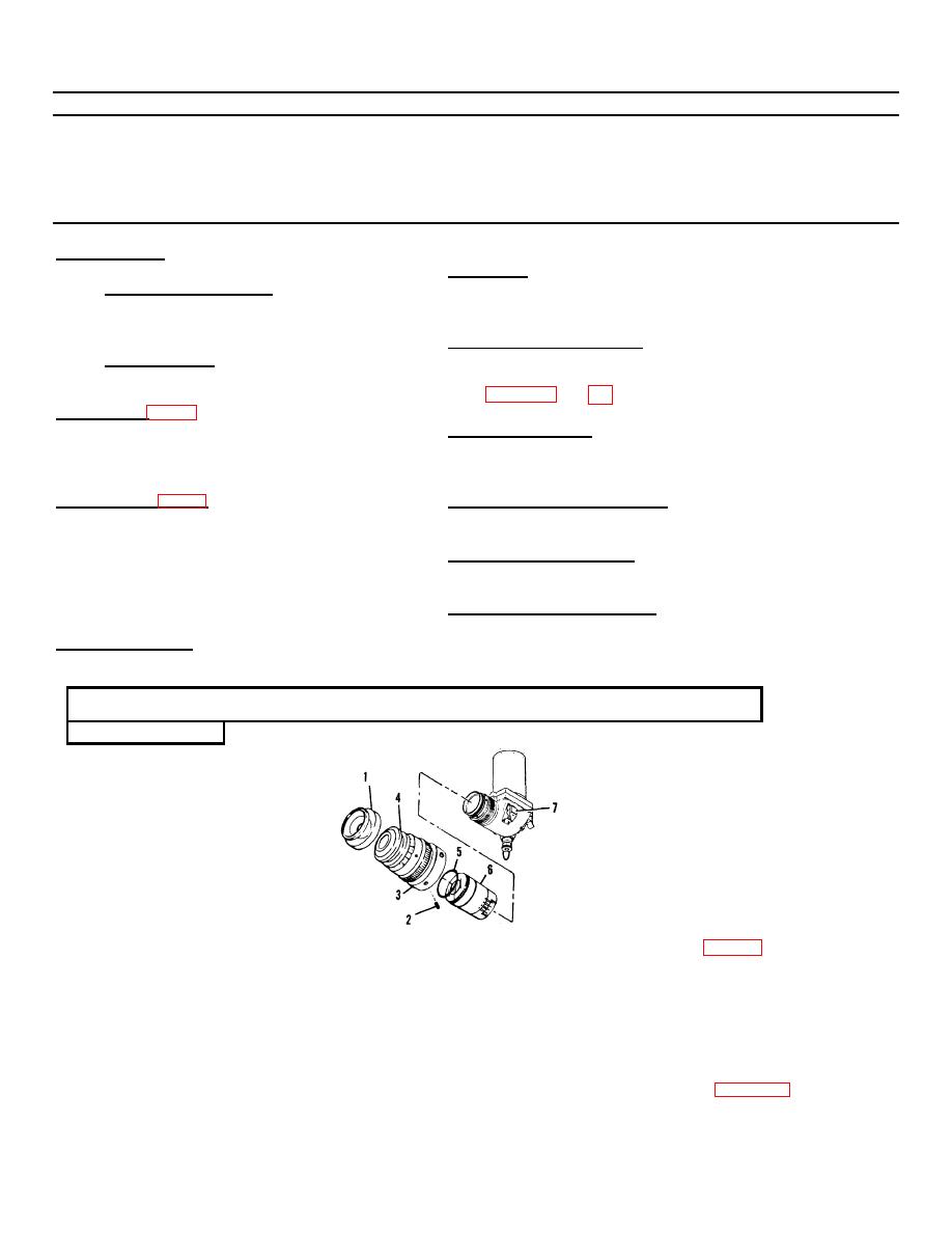
2-4 ELBOW ASSEMBLY
This task covers:
Removal
Inspection/Repair
Disassembly
Reassembly
Cleaning
Installation/Adjustment
INITIAL SETUP
References
Applicable Configuration
None
All
Troubleshooting References
Test Equipment
TM 9-2350-253-10
TS- 3 5 2 B/U Multimeter
TM 9-2350253-20-2
Special Tools (p 1-3)
Equipment Condition
Tube Extractor 1240-01-054-5789
None
Material/Parts (App B)
Special Environment Conditions
Grease MIL-G-4343
None
Sealing Compound MIL-S-11031
Silicone Adhesive (RTV) MIL-A-46106
General Safety Instructions
Solder QQ-S-571
None
Alcohol MIL-STD-1201
Solvent P-D-680
Approximate Time Required
Lens Tissue
See Maintenance Allocation Chart (MAC)
Personnel Required
in TM 9-2350-253-20-2
1
LOCATION
ITEM
REMARKS
ACTION
DISASSEMBLY
Remove
eyeshield
(1).
Elbow
Image
Loosen two set screws (2)
Assembly
Intensifier
on locking ring (3) of
Tube
eyepiece
assembly
(4).
Remove eyepiece assembly
(4) by unscrewing locking
ring
(3).
Remove
the
packing (5) from the slot in
the rear of the eyepiece
assembly (4) covered by
locking ring (3). Use the
tube extractor, (p 1-3), and
CAUTION
Eyeshield (1)
engage the threads on the
The image intensifier tube may be
Setscrew (2)
tube extractor with the
damaged if exposed to bright
Locking Ring (3)
threads on the image
sunlight or brought into close
Eyepiece Assembly (4'
intensifier tube (6) and pull
proximity with high intensity
Packing (5)
straight back. Disengage the
artificial light. Keep shutter
Image
extractor tool from the tube.
Intensifier Tube (6)
Protect ends of tube with
switch in off position while
Shutter Switch (7)
lens tissue.
working on Elbow.
2-6


