
ARMY TM 9-1240-379-34
MARINE CORPS TM 04332A-34
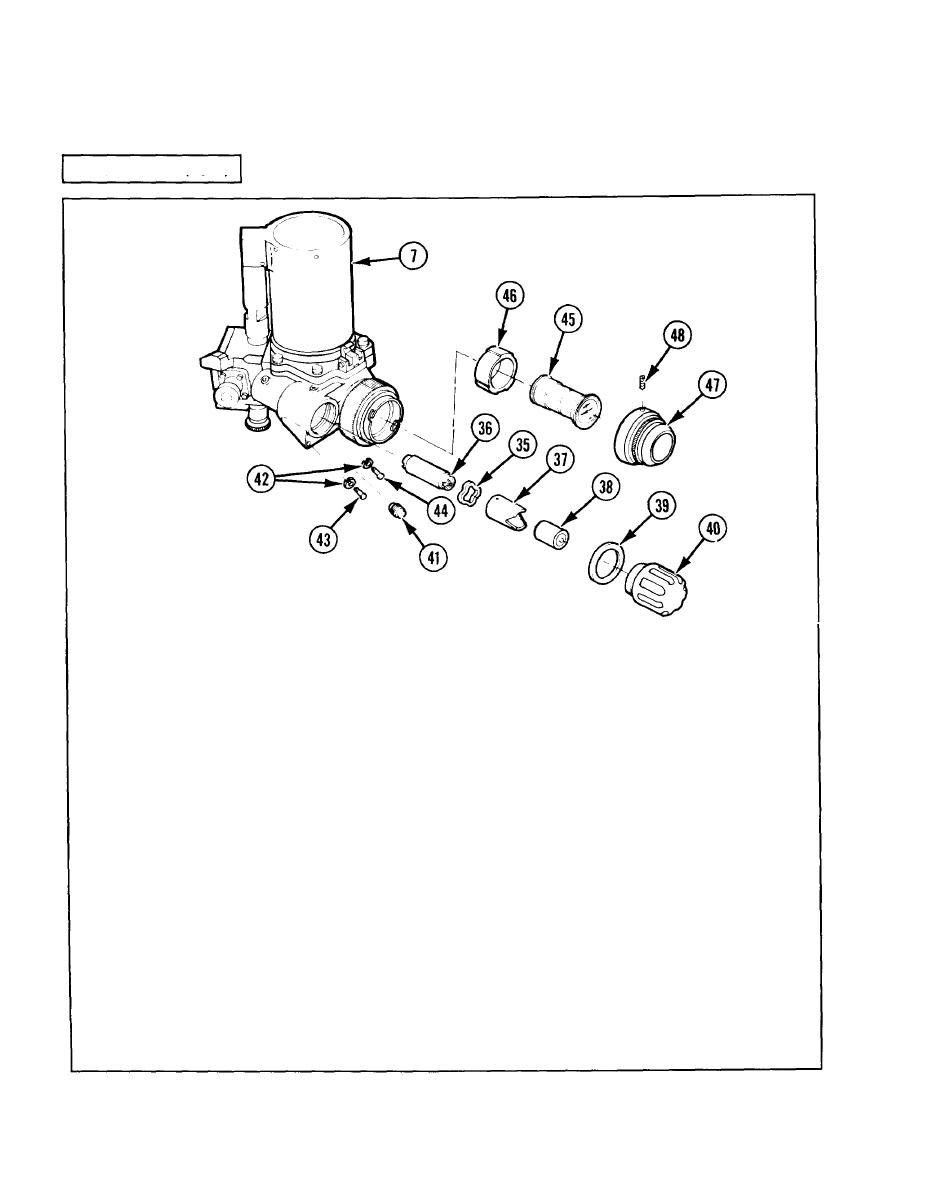
2-5. INFRARED BODY ASSEMBLY - MAINTENANCE INSTRUCTIONS. (cont)
REASSEMBLY (cont)
2 7 If removed, install knob (41), four new
20 Assemble new spring tension washer
lockwashers (42), new machine screw
(35) to input end of solid power supply
(43), and three new machine screws
(36).
(44).
2 1 Aline pins of pinned sleeve (37) to
bayonet-type slots of solid power sup-
CAUTION
ply (36).
Damage may result if electron
tube is exposed to bright
22 Compress spring tension washer (35)
sunlight or high intensity ar-
and rotate pinned sleeve (37) clockwise
tificial light.
to secure.
28 Install electron tube (45) and collar (46)
2 3 Install assembled components in in-
in infrared body assembly (7).
frared body assembly (7), alining
bayonet-type slots with interlocking
29 Install eyepiece assembly (47); tighten
pins of connector; rotate clockwise to
clockwise snugly by hand.
secure.
24 Install converter regulator (38) in pinned
30 Tighten two setscrews (48).
sleeve (37).
31 After maintenance has been completed,
25 Assemble new gasket (39) to cap
purge and charge in accordance with
assembly (40).
TM 750-116.
26 Install cap assembly (40) in infrared
body assembly (7) and tighten.
2-36
