
ARMY TM 9-1240-379-34
MARINE CORPS TM 04332A-34
2-6. OPTICAL CELL ASSEMBLYMAINTENANCE INSTRUCTIONS.
THIS TASK COVERS:
a.
Disassembly
Reassembly
b . Inspection/cleaning/repair
c.
INITIAL SETUP
Applicable Configurations
Ethyl alcohol (item 9, app B)
M32 and M32C tank periscope
Lens paper (item 14, app B)
Tools and Special Tools
References
Helicoil insert and tool kit (4131-04-1)
TM 9-254
Instrument and fire control shop equip-
TM 9-1240-379-34P
ment (SC 4931-95-CL-A07)
TM 750-116
Instrument and fire control system repair
shop equipment (SC 4931-95-CL-A09)
Equipment Conditions
Materials/Parts
moved from tank periscope
Artist's brush (item 3, app B)
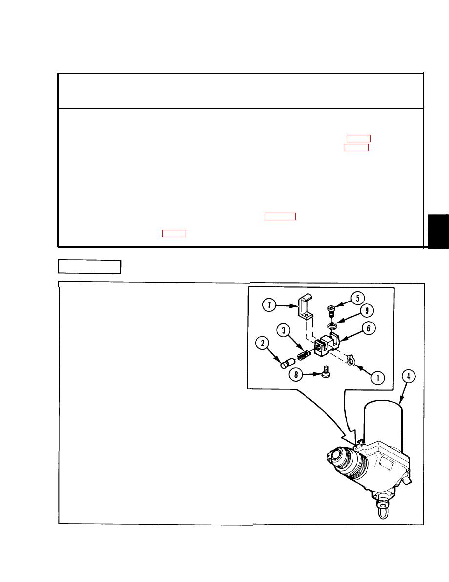
DISASSEMBLY
WARNING
Detent plunger is under spring
tension. Be careful when
removing or injury may result.
1 Remove retaining ring (1) from detent
plunger (2) while pressing a screwdriver
blade against detent plunger to release
spring tension. Remove detent plunger
(2) and helical spring (3) from optical
cell assembly (4).
2 Remove two machine screws (5) and
remove machine key (6) and body
assembly bracket (7).
3 Remove machine screw (8) to separate
body assembly bracket (7) from
machine key (6).
4 Remove two screw thread inserts (9)
only if necessary for replacement. Refer
t o TM 9-254.
2-37
