
TM 9-1240-401-34&P
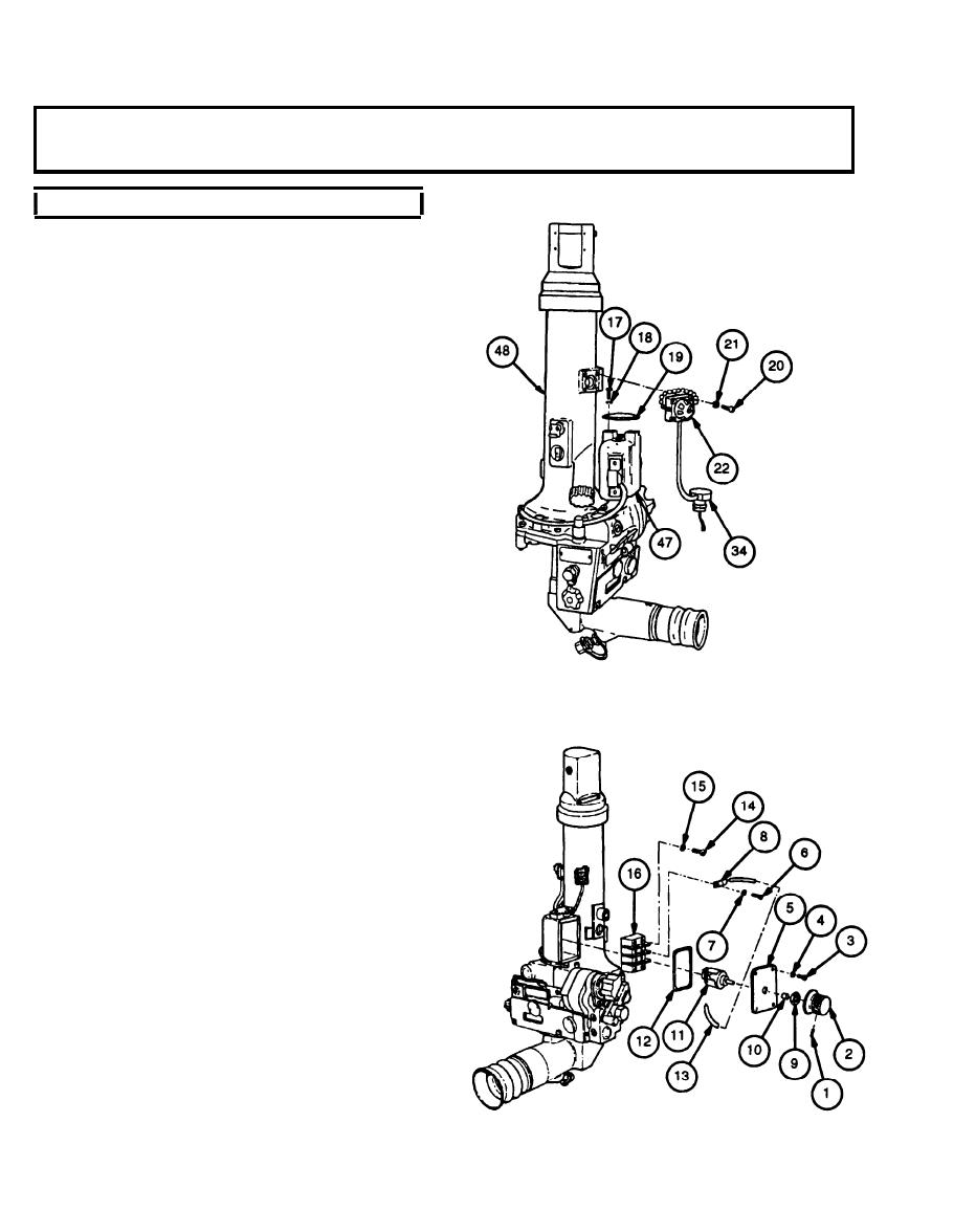
5-15. LAMP ASSEMBLY AND RELATED PARTS (M117A2) MAINTENANCE INSTRUC-
TIONS - continued
c. Assembly/Installation - continued
16
Repeat steps 4 through 15 for second lamp assem-
bly.
17
Install two lamp assemblies (22) on upper housing
(48) and secure with eight new Iockwashers (21)
and eight machine screws (20).
Install plugs (34) in housing (47) and secure with
18
retainer (19), two new Iockwashers (18), and two
machine screws (17).
19
Mount variable resistor (11 ) on access cover (5)
and secure with boot (10) and nut (9).
20
If removed, solder two wires to terminals of vari-
able resistor (11 ) using solder and flux.
21
Apply a coat of adhesive over each terminal lug of
variable resistor (11) to provide proper insulation.
22
Mount variable resistor knob (2) on shaft of vari-
able resistor (11) and secure with setscrew (1).
23
Install terminal board (16) and secure with four new
Iockwashers (15) and four machine screws (14).
24
Solder six terminal strips (8) to six wires (13) using
solder and flux.
25
Install six terminal strips (8) on terminal board (16)
and secure with four new Iockwashers (7) and four
machine screws (6). (Ref. wiring diagram p. 5-23.)
26
Install new preformed packing (12).
27
Install access cover (5) and secure with four new
Iockwashers (4) and four machine screws (3).
28
Purge and charge optics (ref. TM 750-116).
5-24
