
TM 9-1240-401-34&P
I
I
5-15. LAMP ASSEMBLY AND RELATED PARTS (M117A2) MAINTENANCE lNSTRUC-
TlONS
I
a. Removal/Disassembly b. Repair
This task covers:
C.
Assembly/installation
INITIAL SET-UP
Preformed packing (Item 25, appx E)
Preformed packing (Item 26, appx E)
Hot air mini gun (Item 18, appx F)
Preformed packings (Item 21, appx E)
Sealing compound (Item 13, appx B)
Tool Kit, Electronic System, Repair, Field Mainte-
Sleeving, insulation (Fig. C-10, appx C)
nance (SC5180-95-CL-B29)
Sleeving, insulation, non-shrinkable (Fig. C-9,
appx C)
Solder (Item 18, appx B)
Tubular spanner wrench, 11/16 and 45/64 inch
(Item 26, appx F)
References
TM 9-254
TM 750-116
Adhesive (Item 2, appx B)
Flux (Item 5, appx B)
Equipment Condition
Lockwashers (2) (Item 63, appx E)
M117A2 panoramic telescope removed from
Lockwashers (8) (Item 68, appx E)
howitzer (TM 9-2350-31110/
Lockwashers (19) (Item 69, appx E)
TM 9-2350-314-10)
Lockwashers (2) (Item 70, appx E)
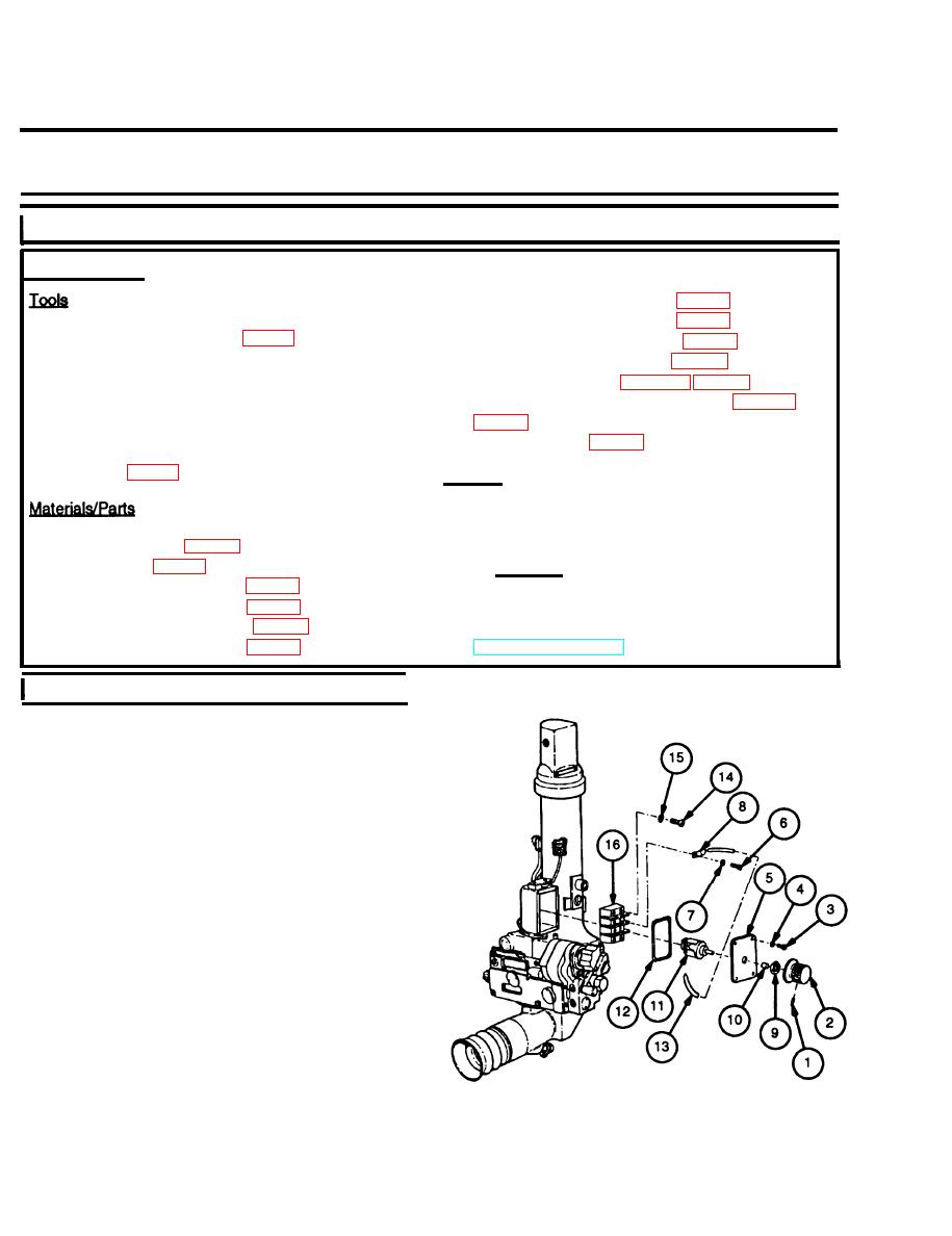
a. Removal/Disassembly
I
1 Remove setscrew (1) and variable resistor knob
(2).
2 Remove four machine screws (3), four Iockwashers
(4), and access cover (5). Discard Iockwashers.
3 Remove four machine screws (6), four Iockwashers
(7), and six terminal strips (8) with wires attached.
Discard Iockwashers.
4 Remove nut (9) and boot (10), from variable resis-
tor (11), then remove variable resistor (11) from
access rover (5).
5 Remove and discard preformed packing (12).
6 Unsolder six terminal strips (8) from six wires (13)
only if necessary to replace damaged parts.
7 Remove four machine screws (14), four lock-
washers (15), and terminal board (16). Discard
Iockwashers.
5-20
