TM 9-1240-401-34&P
3-29. M118A2/M118A3 ELBOW TELESCOPE FINAL INSPECTION AND ADJUSTMENT
- continued
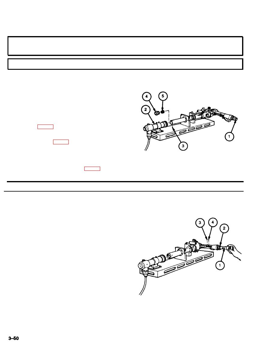
c. PARALLAX ADJUSTMENT
1
View through M118A2/M118A3 elbow telescope
eyepiece (1) and move head from side to side. Ap-
parent movement between telescope reticle
crosslines and target image should not exceed
0.15 mil (the width of reticle line) as measured on
collimating projector (2) reticle.
2
If error exists, remove setscrew (3).
3
Using 2 and 2-1/64 inch tubular spanner wrench
(Item 33, appx F), remove cell assembly (4).
4
Using 1-7/16 and 1-29/64 inch tubular spanner
wrench (Item 30, appx F), make adjustment to cell
(5) by rotating cell (5) until reticle crosslines are
parallel.
5
Install cell assembly (4) using 2 and 2-1/64 inch
tubular spanner wrench (Item 33, appx F).
6
Install setscrew (3).
d. EYEPIECE FOCUS ADJUSTMENT
1
Rotate eyepiece of dioptometer (1) until reticle
lines of dioptometer are in sharp focus.
2
Place dioptometer (1) in front of M118A2/M118A3
elbow telescope eyepiece (2).
3
Look through dioptometer (1) and slide dioptometer
objective back and forth until M118A2/M118A3 el-
bow telescope reticle lines appear sharp and clear.
4
Remove dioptometer (1), without disturbing its set-
ting, and note reading on side of dioptometer. Eye-
piece focus, as indicated on dioptometer (1),
should be-0.75 to-1.0 diopter.
5
If error exists, remove setscrews (3 and 4) from
eyepiece arm.
6
Make adjustment to cell assembly through hole
where larger setscrew (4) was removed.
7
Recheck eyepiece focus.
8
Install setscrews (3 and 4). Do not overtighten.


