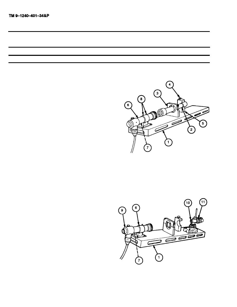
3-29. M118A2/M118A3 ELBOW TELESCOPE FINAL INSPECTION AND ADJUSTMENT
- continued
a. SETTING UP TELESCOPE FIXTURE
Place telescope fixture (1) on a level surface at a
1
height suitable for viewing through telescopes.
2
Place test bar assembly (2) in position on tele-
scope fixture (1), making certain that the test bar
spherical ring is seated in the forward clamping
block (3).
Insert tapered pin (4) through adapter block (5) and
3
into test bar assembly (2). Secure tapered pin (4).
Install collimating projector (6) in its holder on tele-
4
scope fixture (1), with vertical reticle line approxi-
mately plumb.
Remove diffusion disk (7) from collimating projector
5
(6).
6
View through the collimating projector (6) and en-
sure the horizontal and vertical lines of the
collimating projector (6) reticle, as reflected by the
mirror in the test bar assembly (2), are superim-
posed on each other. If not, adjust screws (8) on
collimating projector (6) holder until the lines are
superimposed.
7
Remove test bar assembly (2) from telescope fix-
ture (1).
8
Replace diffusion disk (7) in collimating projector
(6). Replace light source (9).
9
Install collimating telescope (10) in collimating tele-
scope holder (11).
Adjust height of collimating telescope (10) until
10
reticle crosslines are superimposed on the reticle
crosslines of collimating projector (6).
11
Suspend plumbline to one side of telescope fixture
(1), approximately 30 feet (9.14 m) from collimating
telescope (10).
3-48


