
TM 9-1240-400-34&P
2-14.
MAINTENANCE OF ADAPTER ASSEMBLY AND COUNTER ASSEMBLY (CONT).
REMOVAL/DISASSEMBL Y (CONT)
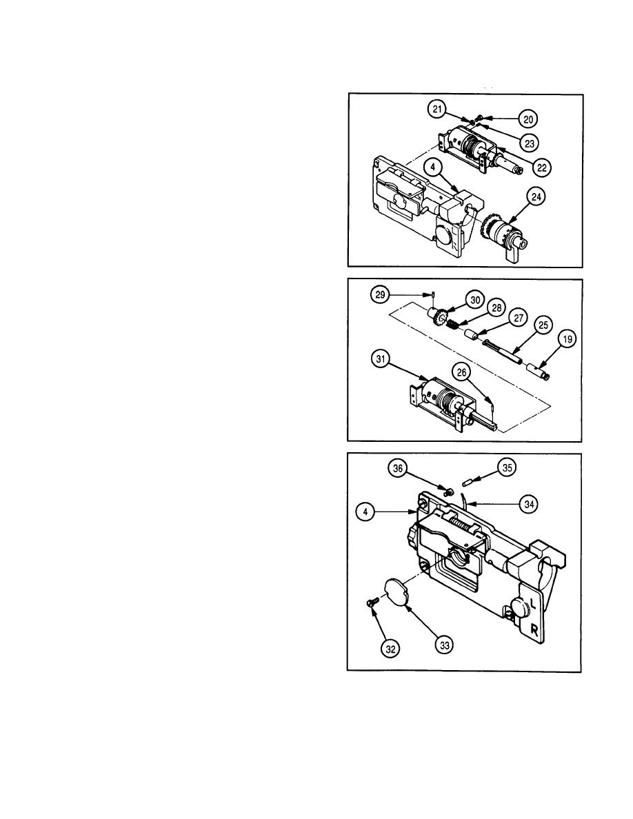
NOTE
Steps 7, 9, and 10 are written and
illustrated for removal and disassembly
of counter assembly.
Remove pins only if damaged.
7
Remove two screws (20), two lockwashers (21),
counter assembly (22), and two pins (23) from
adapter (4).
8
Remove differential gear (24).
NOTE
Depress key shaft (25) and rotate
gearshaft (19) to gain access to pin (26).
9
Remove pin (26), gearshaft (19), key shaft (25),
clutch half (27), and spring (28).
10 Remove tapered pin (29) and spur gear (30) from
rotating counter (31).
11 Remove two screws (32) and cap (33) from adapter
(4).
13 Remove contact (35) and plug (36).
2-44
