ARMY TM 9-1240-379-34
MARINE CORPS TM 04332A-34
3-7. SWITCH ASSEMBLYMAINTENANCE INSTRUCTIONS. (cont)
REASSEMBLY
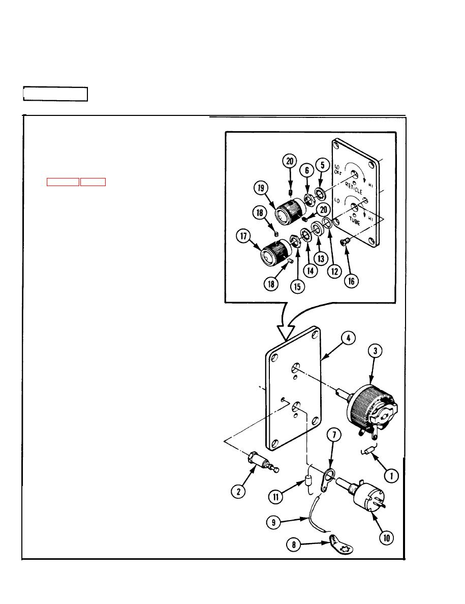
1 Fabricate replacement electrical wire
2 Attach fixed resistor (1) to stud ter-
minal (2) and RETICLE variable resistor
(3) using solder.
3 Secure RETICLE variable resistor (3) to
plate (4) with lockwasher (5) and nut
(6).
4 Attach terminal lugs (7) and (8) to wire
(9) using solder.
5 Install ground strap on TUBE variable
resistor (10).
6 Attach fixed resistor (11) to terminal
lug (7) and TUBE variable resistor (10)
using solder.
7 Secure TUBE variable resistor (10) to
plate (4) with packing (12), spacer (13),
lockwasher (14), and nut (15).
8 Install stud terminal (2) and machine
screw (16).
9 Install TUBE control knob (17) and
tighten two setscrews (18).
10 Install RETICLE control knob (19) and
tighten two setscrews (20).
11 After maintenance has been completed,
purge and charge in accordance with
T M 750-116.
3-22


