ARMY TM 9-1240-379-34
MARINE CORPS TM 04332A-34
2-7. ELBOW ASSEMBLY-MAINTENANCE INSTRUCTIONS. (cont)
REASSEMBLY
(cont)
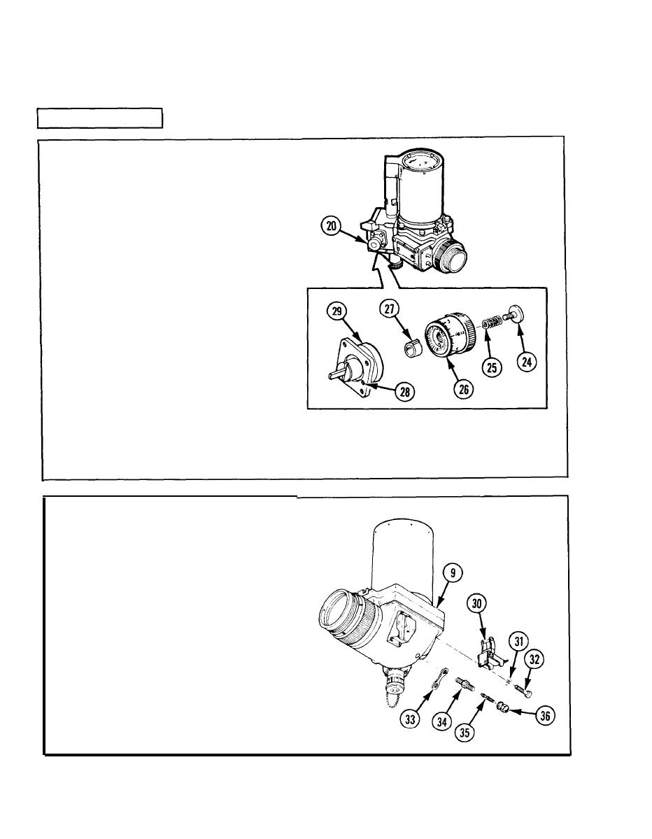
13 Adjust deflection boresight knob
assembly (20):
a. Remove screw (24) and spring (25).
b . Remove knob (26) with scale at-
tached. Dot not remove scale.
c. Set stop (27) against right-hand
side of pin (28) in clutch (29).
d . Install knob (26) so that pin is as
close as possible against left-hand
side of stop (27).
e. Install spring (25) and screw (24);
tighten screw (24).
f. Turn knob (26) clockwise to its
limit. Loosen screw (24) and rotate
diopter scale to read +4.0. Tighten
screw (24).
loosen screw (24) and turn diopter
g. Turn knob (26) counterclockwise to
scale so that 0 is midpoint of the
its limit. The diopter scale should
knob rotation. Tighten screw (24).
read -4.0. If it does not read -4.0,
14 Install periscope latch (30), two
lockwashers (31), and two machine
screws (32).
15 Assemble valve cap strap (33) to
tapered thread end of purging valve
stem (34).
16 Apply sealing compound to tapered
thread end of purging valve stem (34).
17 Install purging valve stem (34) in valve
assembly (9) and tighten.
18 Install valve core (35) in purging valve
stem (34).
19 Assembly pneumatic valve cap (36) to
loose end of valve cap strap (33) and
install on purging valve stem (34).
2-44


