ARMY TM 9-1240-379-34
MARINE CORPS TM 04332A-34
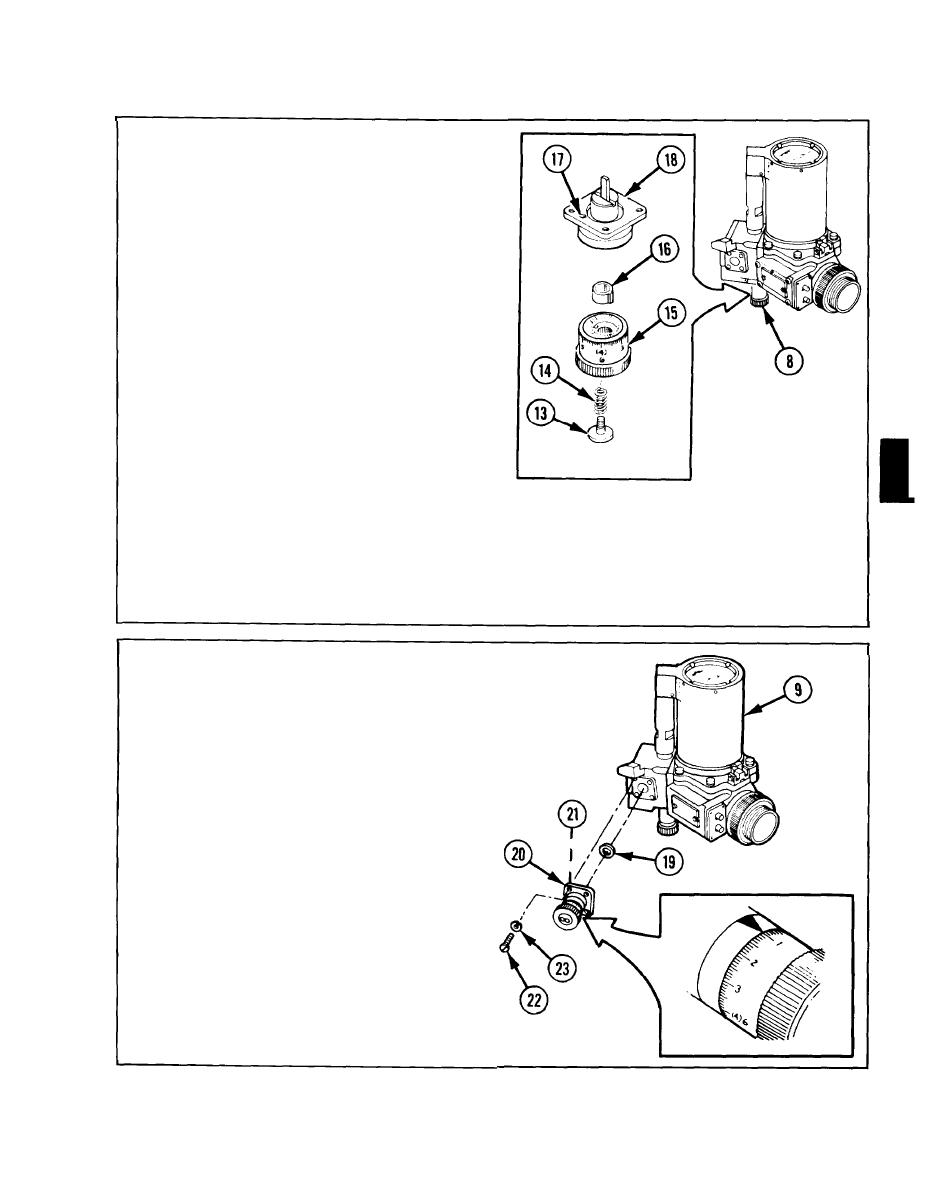
8 Adjust elevation boresight knob
assembly (8):
a. Remove screw (13) and spring (14).
b. Remove knob (15) with scale at-
tached. Do not remove scale.
c. Set stop (16) against right-hand
side of pin (17) in clutch (18).
d. Install knob (15) so that pin is as
close as possible against left-hand
side of stop (16).
e. Install spring (14) and screw (13);
tighten screw (13).
f. Turn knob (15) clockwise to its
limit. Loosen screw (13) and rotate
diopter scale to read +4.0. Tighten
screw (13).
g. Turn knob (15) counterclockwise to
loosen screw (13) and turn diopter
its limit. The diopter scale should
scale so that 0 is midpoint of the
read -4.0. If it does not read -4.0,
knob rotation. Tighten screw (13).
9
Apply a light coat of grease to new
preformed packing (19).
10 Install new preformed packing (19) into
grooved recess of deflection boresight
knob assembly (20).
11 Holding deflection boresight knob
assembly (20) against elbow assembly
(9), turn knob so that adjuster blade
(21) just touches reticle housing.
NOTE
If adjuster blade (21) extends
too far, the spring tension of
the reticle will force the deflec-
tion knob assembly outward.
12 Install four machine screws (22),
assembled with four lockwashers (23),
and tighten.
2-43


