
TM 9-1240-401-34&P
5-23. ADAPTER ASSEMBLY MAINTENANCE INSTRUCTIONS - continued
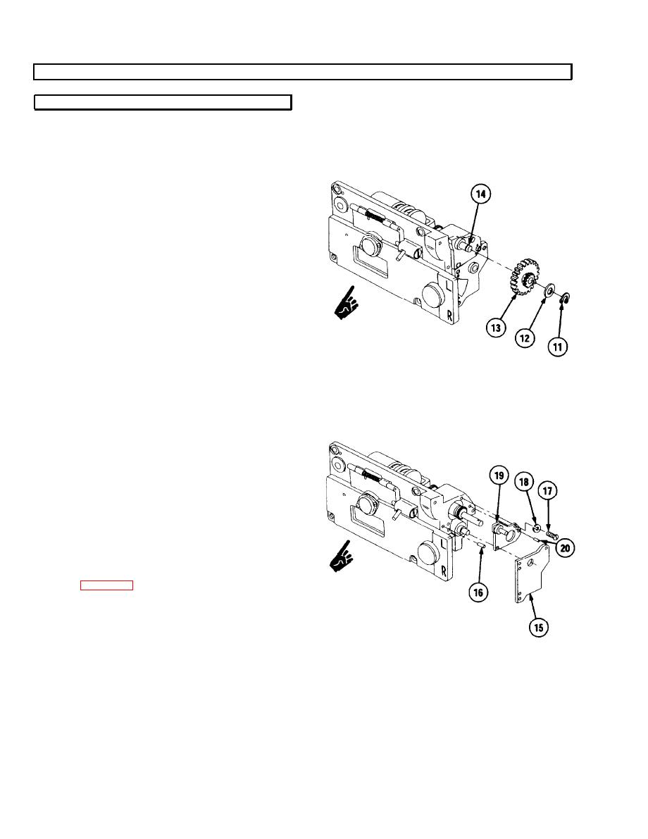
a. Removal/Disassembly - continued
5
Remove retaining ring (11), washer (12), and gear
cluster (13) from shaft (14).
6
Remove gear assembly plate (15) and two headless
straight pins (16). Remove two headless straight
pins only if damaged.
7
Remove three machine screws (17) and three
lockwashers (18). Discard lockwashers.
8
Remove plate (19). Remove two headless straight
pins (20), only if damaged.
9
Remove two machine screws (21), two lockwashers
(22), and reset counter assembly (23) from adapter
assembly (10). Discard lockwashers.
NOTE
See para 5-24 for disassembly of reset
counter assembly (23).
10
Remove differential gear assembly (24).
11
Remove two headless straight pins (25) only if
damaged.
5-40
Change 1
