TM 9-1240-400-34&P
4
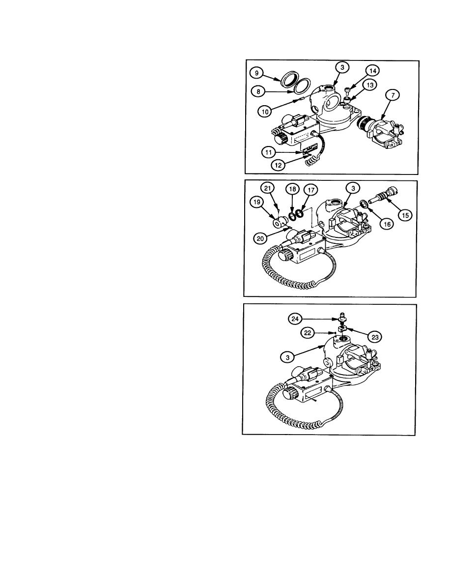
Apply a light coat of aircraft grease (item 8, appx C)
to support assembly (7).
5
Using adjustable spanner wrench, install support
assembly (7), shim (8) if removed, and plain round
nut (9).
6
Install setscrew (10) in adapter (3).
7
Install identification plate (11) and two screws (12).
8
Install control cam (13) and new self-locking screw
(14).
9
Apply a light coat of aircraft grease (item 8, appx C)
to worm shaft (15).
10
Install worm shaft (15) and spacer (16), meshing
11
Install shim (17) if removed, spacer (18) and collar
(19) to worm shaft (15).
12
Install setscrew (20) in collar (19), leaving worm
shaft (15) to turn without binding.
13
If necessary, drill and ream collar (19) and install
tapered pin (21). Remove setscrew (20). Refer to
TM 9-254.
14
If removed, install pin (22).
15
Install receptacle (23) and shaft (24) in adapter (3).
4-9


