
TM 9-1240-400-34&P
2-17.
M115 PANORAMIC TELESCOPE FINAL INSPECTION INSTRUCTIONS (CONT).
IMAGE TILT ADJUSTMENT (CONT)
NOTE
Rotate deflection knob to gain access
to each setscrew.
Azimuth ring may be rotated to aline
reticles and avoid optic cell assembly
movement.
9
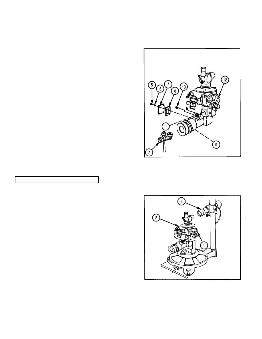
While rotating deflection knob (12), loosen three
setscrews (11) on retaining ring of optic cell
assembly (9).
10
Rotate optic cell assembly (9) by hand, until
image is plumb when sighting through
dioptometer (2).
11
Tighten three setscrews (11).
12
Apply sealing compound (item 10, appx C) to
threads of setscrew (10).
13
Install setscrew (10) in plug hole until flush.
14
Install gasket (8), access cover (7), four
lockwashers (6), and four machine screws (5).
PARALLELISM OF RETICLE AND IMAGE
1
Perform image tilt adjustment. Refer to page 2-
65.
NOTE
Make sure numbers in
projector
collimator are right side up.
2
Rotate deflection knob (1) until reticle of M115
panoramic telescope (2) line coincides with
reticle of projector collimator (3). The opposite
extremity should place reticles in coincidence
within 30 minutes (9.5 mils) of arc as measured
on projector collimator (3). If specified tolerance
is not met, go to step 3.
2-66
