
TM 9-1240-400-34&P
2-17.
M115 PANORAMIC TELESCOPE FINAL INSPECTION INSTRUCTIONS (CONT).
PARALLAX ADJUSTMENT
1
Check for allowable parallax of 0.15 mil using
preset target of 130 meters + 10 meters. If
parallax exceeds limit, go to step 2.
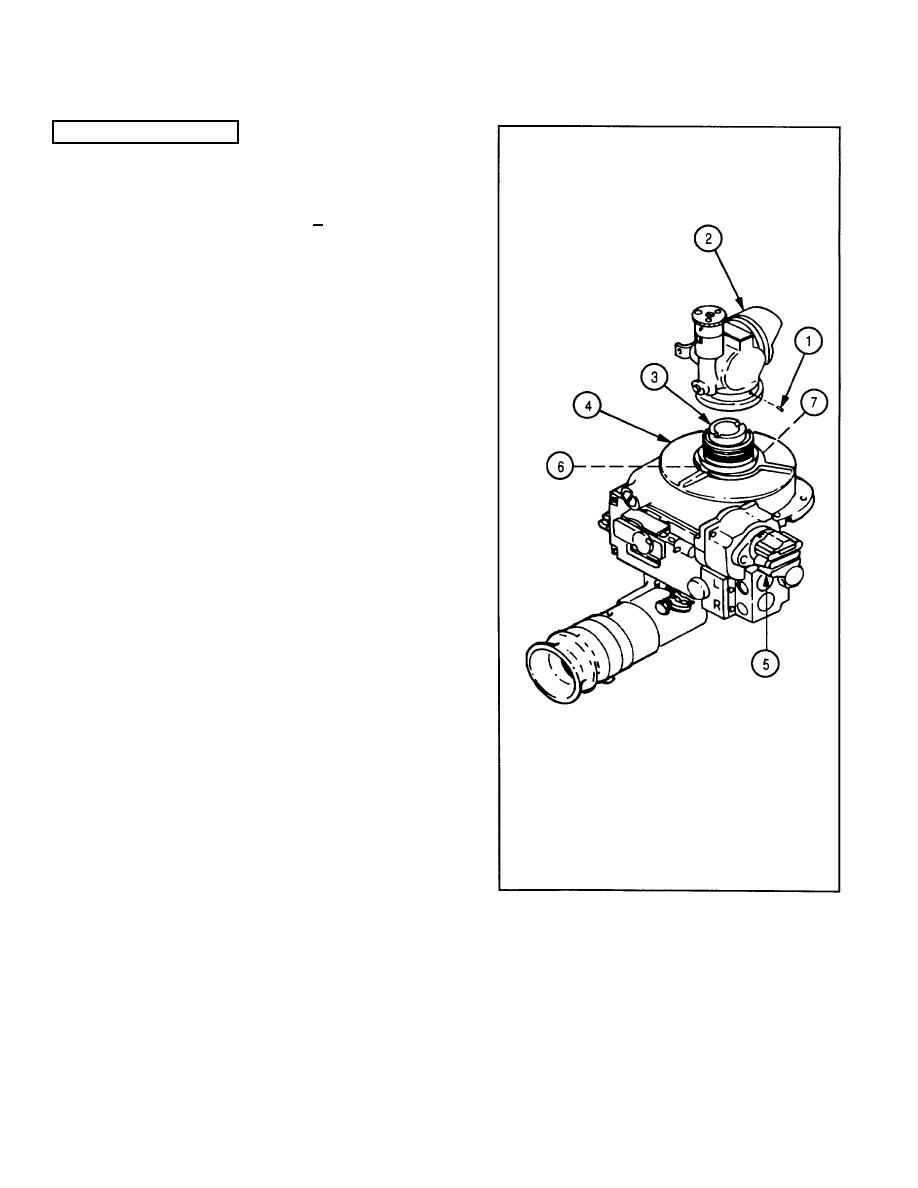
2
Remove three setscrews (1) and head assembly
(2), rotating head assembly counterclockwise.
3
Scribe a coinciding line on worm gear assembly
(3) from cover (4).
4
Rotate deflection knob (5) to gain access to
setscrew (6) through cover (4).
5
Remove setscrew (6) and turn objective cell (7)
a small amount in either direction.
6
Temporarily install head assembly (2) and
observe parallax. Adjust objective cell as
required.
7
Apply sealing compound (item 10, appx C) to
threads of setscrews (6).
8
Aline scribe marks on cover (4) and worm gear
assembly (3) and install setscrew (6).
9
Install head assembly (2).
10
Using torque wrench and torque adapter (figure
4, appx D), tighten head assembly (2) to 80.00
in.-lb (9.04 N-m).
11
Apply sealing compound (item 10, appx C) to
threads of three setscrews (1).
12
Install three setscrews (1).
2-64
