
TM 9-1240-401-34&P
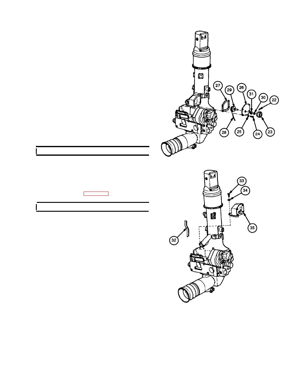
12 Remove setscrew (22) and variable resistor knob
(23).
13 Remove four machine screws (24), four lock-
washers (25), access cover (26), and gasket (27).
Discard Iockwashers and gasket.
14 Unsolder wires (28) from variable resistor (29).
15 Remove nut (30) and boot (31) from variable resis-
tor (29).
16 Remove variable resistor (29) from access cover
(26).
17 Remove tube (32).
18 Remove three machine screws (33), three lock-
washers (34), and housing (35). Discard lock-
washers.
I
b. Repair
1
Remove corrosion, grease, and dirt from all parts.
Refer to TM 9-254 for cleaning instructions.
2 Visually inspect for missing or damaged parts.
3 Repair or replace parts in accordance with author-
ized parts listed in appendix D.
c. Assembly/installation
I
1
Install housing (35) and secure with three new
Iockwashers (34) and three machine screws (33).
Install wire (28) in tube (32) and install tube into
2
opening of housing (35).
Mount variable resistor (29) on access cover (26)
3
and secure with boot (31) and nut (30).
Solder wires (28) to lug terminals of variable resis-
4
Apply grease to new gasket (27).
5
Install access cover (26) and gasket (27) on hous-
6
ing (35) and secure with four new Iockwashers (25)
and four machine screws (24).
Install variable resistor knob (23) on shaft of vari-
7
able resistor (29) and secure with setscrew (22).
5-17

