
TM 9-1240-401-34&P
e. Installation
1 If two headless straight pins (7) were removed,
redrill using No. 32 (0.116) drill. Drill into housing
7/8 inch (22.23 mm) deep; ream for drive fit in
outer sleeve (22) and slip fit in worm shaft assem-
bly (3).
2 Install three new shims (4,5, and 6) as required to
obtain minimum backlash. Apply grease (item 6,
appx B) to teeth of worm shaft assembly (3) and
position over two headless straight pins (7). Secure
with three new Iockwashers (2) and three cap
screws (1).
3-16. COVER ASSEMBLY MAINTENANCE INSTRUCTIONS (M118A3)
d. Assembly e. Installation
This task covers:
a. Removal b. Disassembly c. Repair
INITIAL SET-UP
Sealing Compound (Item 13, appx B)
Tools
Shim (Item 49, appx E)
Tool Kit, Electronic System, Repair, Field Mainte-
References
nance (SC5180-95-CL-B29)
TM 9-254
TM 750-116
Equipment Condition
I
Adhesive (Item 1, appx B)
M118A3 elbow telescope removal from howitzer
Lockwashers (4) (Item 68, appx E)
(TM 9-2350-311-10)
Preformed packing (Item 42, appx E)
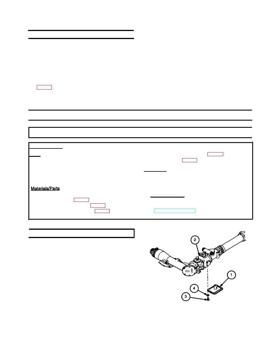
a. Removal
Remove cover assembly (1) from housing (2) by remov-
ing four machine screws (3) and four Iockwashers (4).
Discard lockwashers.
3-19

