
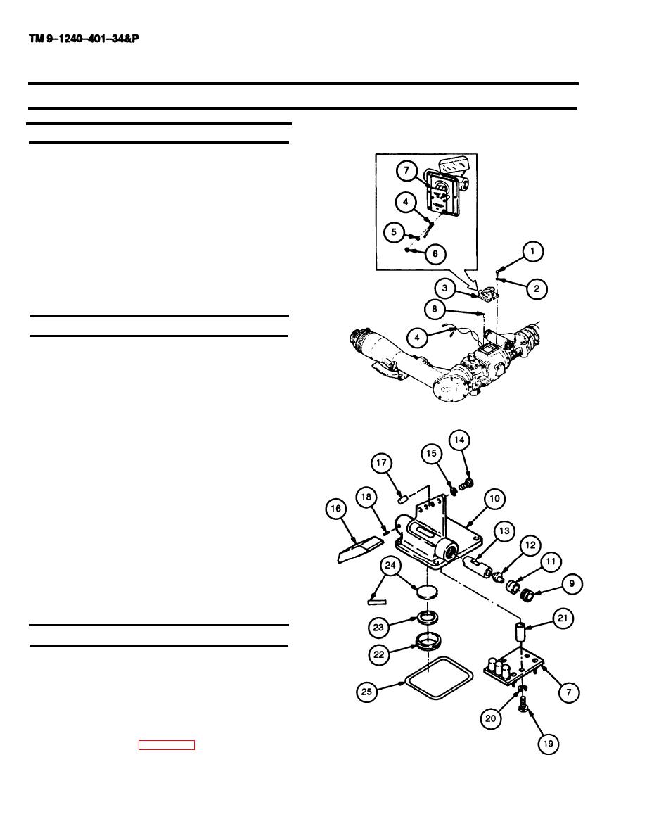
3-18. LEVEL ASSEMBLY MAINTENANCE INSTRUCTIONS (M118A3) - continued
a. Removal
1
Remove four machine screws (1) and four lock-
washers (2). Discard Iockwashers.
Remove level assembly (3).
2
3
Using tape, tag and disconnect wires (4) by remov-
ing two Iockwashers (5) and two nuts (6) from cir-
cuit board assembly (7). Discard lockwashers.
4
Remove two headless straight pins (8) only if dam-
aged.
b. Disassembly
Remove threaded ring (9) from mount (10).
1
2
Remove holder (11), cam (12), and level (13).
3
Remove two cap screws (14), two Iockwashers
(15), and mirror (16). Discard Iockwashers.
4
Remove two headless straight pins (17 and 18)
only if damaged.
5
Remove two machine screws (19), two lock-
washers (20), circuit board assembly (7), and two
sleeve spacers (21).
Using 1-25/32 and 1-51/64 inch tubular spanner
6
wrench, remove retainer (22), shim (23), and win-
dow (24). Discard shim.
7
Remove preformed packing (25) from mount (10)
and discard.
c. Repair
1 Remove corrosion, grease, and dirt from all parts.
Refer to TM 9-254 for cleaning instructions.
2 Visually inspect for missing or damaged parts.
3 Repair or replace parts in accordance with author-
ized parts listed in appendix D.
3-24

