
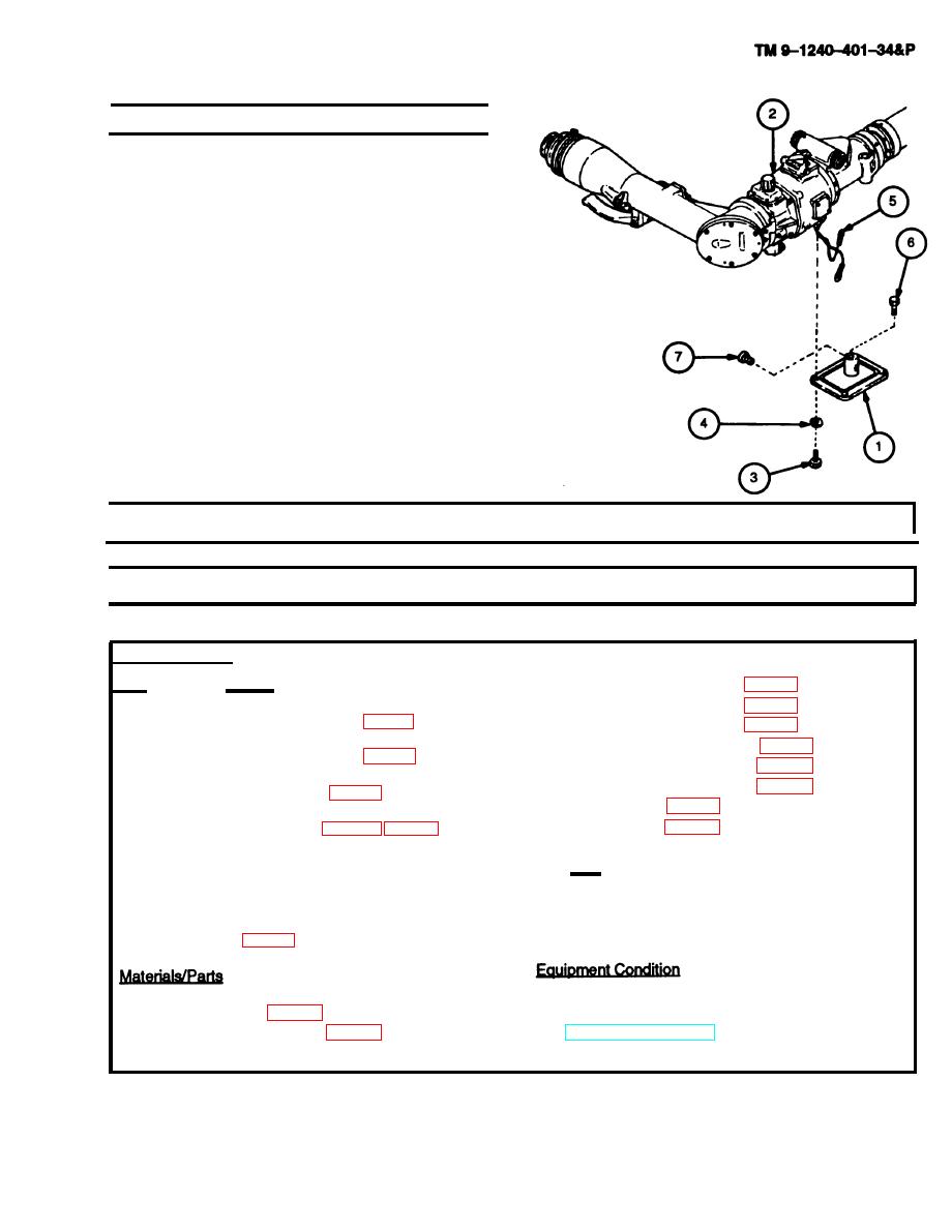
e. Installation
1 Position cover assembly (1) on bottom of housing
(2). Attach wires from wiring harness (5) and se-
cure with machine screws (6 and 7). Remove tags.
2 Secure cover assembly (1) to housing (2) with four
new Iockwashers (4) and four machine screws (3).
3-18. LEVEL ASSEMBLY MAINTENANCE INSTRUCTIONS (M118A3)
d. Assembly e. Installation f. Adjustment
This task covers:
a. Removal b. Disassembly c. Repair
INITIAL SET-UP
Lockwashers (4) (Item 68, appx E)
Tools and Special Tools
Lockwashers (2) (Item 75, appx E)
Drill bit no. 44 (0.086) (Item 15, appx F)
Lockwashers (2) (Item 76, appx E)
Preformed packing (Item 39, appx E)
Drill bit no. 54 (0.055) (Item 16, appx F)
sealing compound (Item 13, appx B)
Sealing compound (Item 15, appx B)
Drill, electric 1/2" (Item 12, appx F)
Shim (Item 49, appx E)
Tape (Item 20, appx B)
Eccentric tool, fabricated (fig. C-3, appx C)
Tool Kit, Electronic System, Repair, field Mainte-
References
nance (SC5180-95-CL-B29) 5180-01-168-0487
TM 9-254
Tubular spanner wrench, 1-25/32 and 1-51/64
TM 750-116
inch (Item 32, appx F)
M118A3 elbow telescope removed from howitzer
Adhesive (Item 2, appx B)
Lockwashers (2) (Item 61, appx E)
(TM 9-2350-311-10)
3-23
