
TM 9-6650-222-35
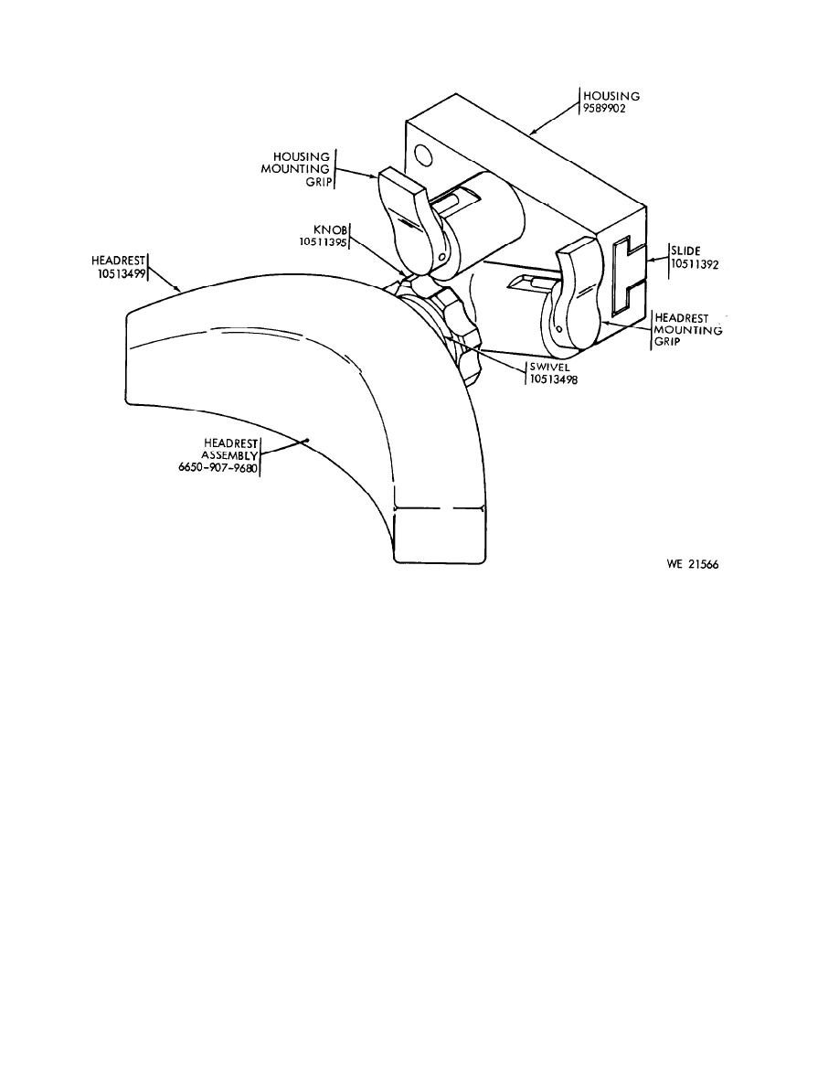
Figure 6-1. Headrest assembly 6650-907-9679.
Section II. REPAIR OF HEADREST ASSEMBLY 6650-907-9679
6-3. Inspection
g. Ensure that the spring-loaded plunger
properly engages the headrest assembly sup-
a. Note the general appearance of the head-
port when the headrest assembly is installed.
rest assembly to determine the type of treat-
h. Check for the smooth and position op-
ment it has received.
eration of housing mounting orip.
b. Inspect the padding on the headrest for
i. Ensure that the spring-loaded plunger
tears, cuts, or other signs of damage that
properly engages the slide when the housing
would render it unserviceable.
is mounted.
c. Ensure that the padding is properly and
j. Ensure that the stop pin is installed on
securely cemented to the headrest plate.
the slide and that the housing strikes the stop
d. Check for smooth and positive position-
when it is installed.
ing of the headrest.
e. Ensure that the knob is free to turn and
k. Ensure that the complete assembly is free
that it will tighten and loosen the headrest
from dirt and grit.
in the swivel mount.
1. Refer to Basic Issue Items List in TM
f. Check for the smooth and positive oper-
9-2350-230-12 and check for completeness of
ation of the headrest mounting grip.
repair parts, tools and equipment.
6-2

