
TM 9-1240-401-34&P
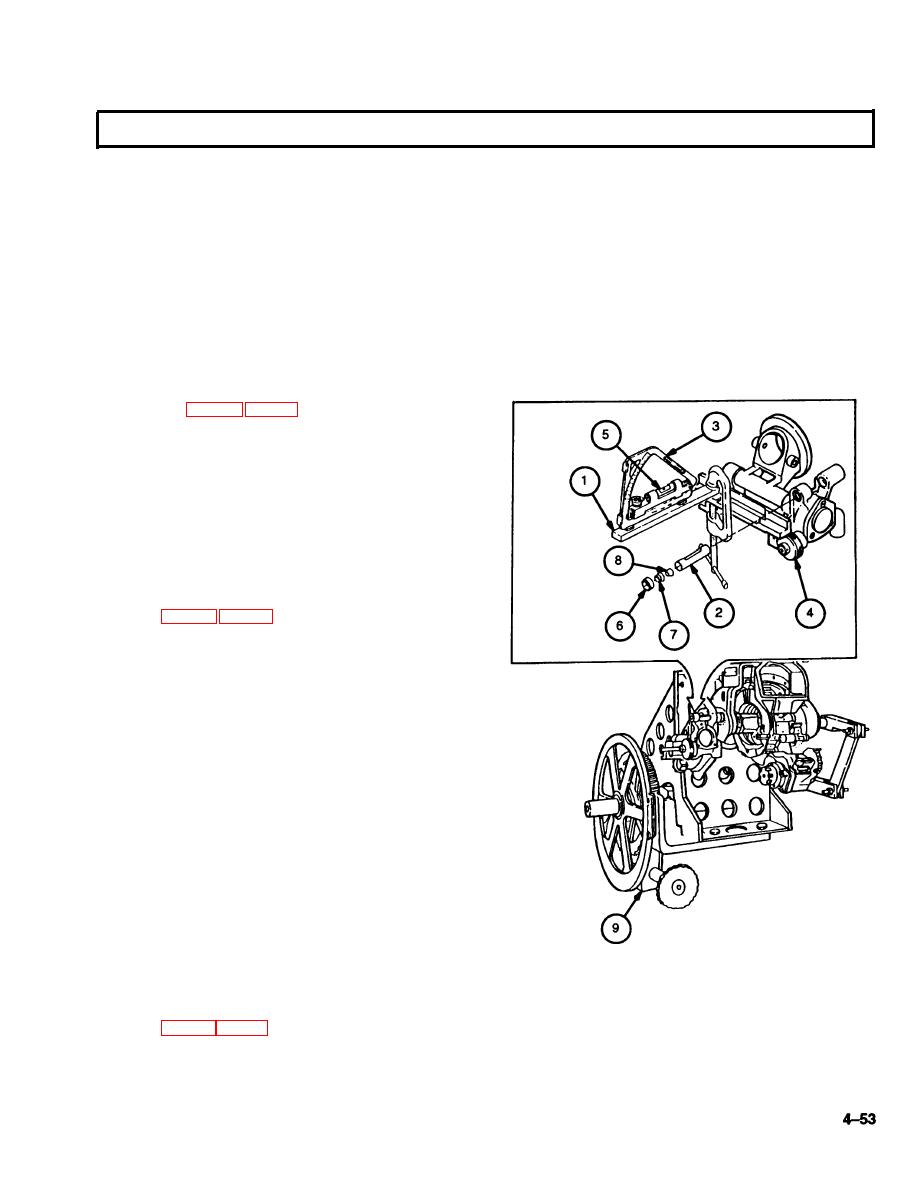
d. QUADRANT SUPPORT ASSEMBLY ADJUSTMENT
1
Clamp a 3/8- by 3/4- by 6-inch parallel bar (1) to
quadrant seat of bracket parallel to the quadrant
support assembly level (2).
Position a zeroed M1A1 gunner's quadrant (3) on
2
parallel bar (1), parallel to quadrant support level
(2).
Adjust quadrant support assembly level knob (4)
3
until gunner's quadrant level (5) bubble is centered.
Remove threaded ring (6) using fabricated eccen-
4
tric tool (fig. C-3, appx C).
Apply sealing compound to threaded ring (6) and
5
install in bracket.
6
Engage fabricated eccentric tool in holder (7) and
threaded ring (6).
7
Insert a common straight blade screwdriver
through the center hole in the fabricated eccentric
tool (fig. C-3, appx C) and engage control cam (8).
Adjust control cam (8) and threaded ring (6) until
8
the level (2) bubble is centered within the gradu-
ations on the level (2).
9
Rotate cross-leveling fixture (9) from 0 to 1330 mils
and adjust control cam (8) and threaded ring (6)
until the level (2) bubble is centered within the
graduations on the level (2).
10
Rotate cross-level fixture (9) from 1330 mils to 0
and adjust control cam (8) and threaded ring (6)
until the level (2) bubble is centered within the
graduations on the level (2).
11
Repeat steps 9 and 10 as necessary to center level
(2) bubble at 0 and 1330 mils.
12
Hold the inner portion of the fabricated eccentric
tool (fig. C-3, appx C) firmly in place while turning
the outer portion of the tool to tighten threaded ring
(6). Be careful not to disturb the setting of level (2).

