
TM 9-1240-401-34&P
I
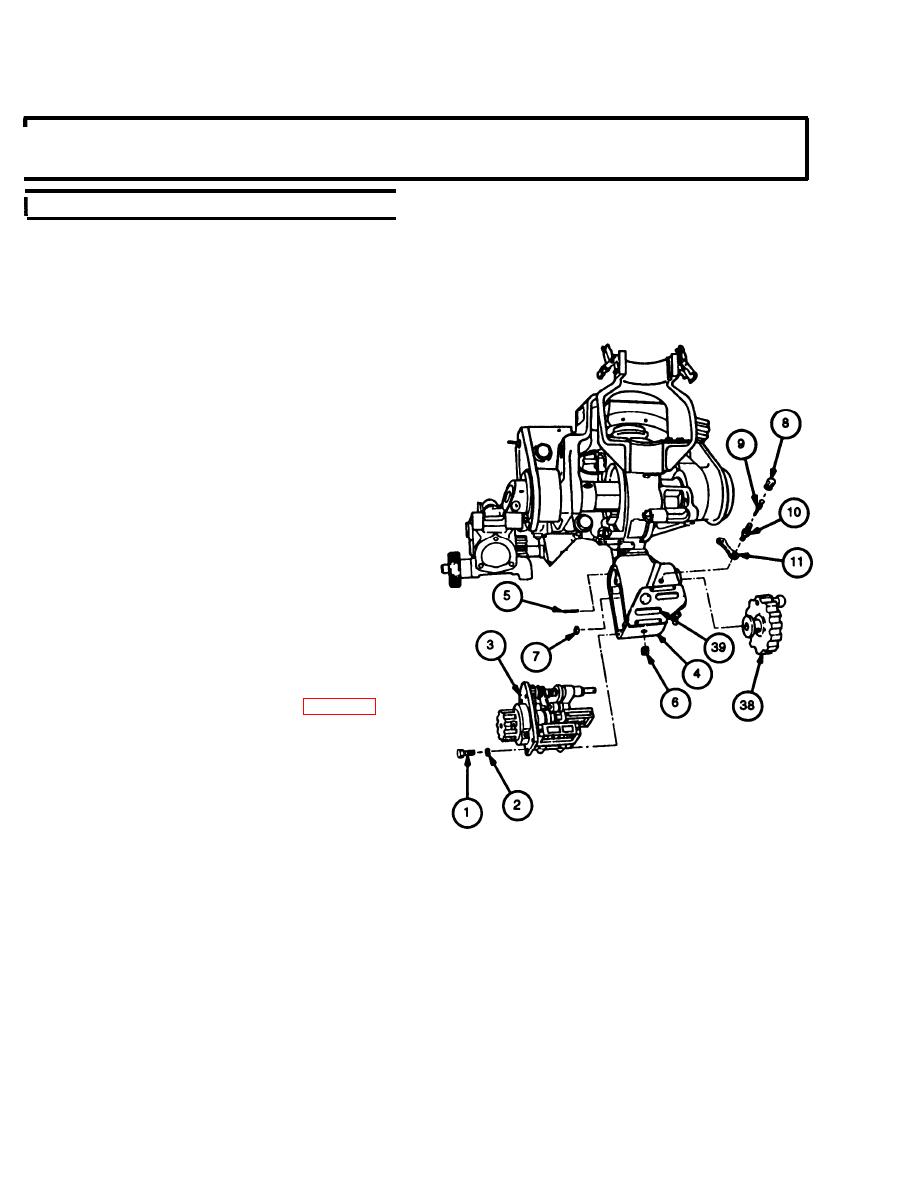
4-21. COUNTER BOX ASSEMBLY (COUNTERS) MAINTENANCE INSTRUCTIONS
- continued
I
c. Assembly - continued
NOTE
If the counter box assembly has a tapped hole
to screw purging valve stem into, nut (7) is not
required.
25
Apply sealing compound to threads of nut (7) and
purging valve stem (10).
Install retaining strap (11), purging valve stem (10),
26
nut (7), valve core (9), and air valve cap (8).
If removed, install plug (6).
27
If removed, install two headless straight pins (5).
28
Install cover (3) with related parts on counter box
29
assembly (4) and secure with four new lock-
washers (2) and four machine screws (1).
Install elevation handwheel (38) (ref. para 4-17).
30
Using elevation handwheel (38), set correction
31
counter (39) to 0000. Rotate elevation handwheel
(38) counterclockwise and ensure correction
counter (39) attains a minimum reading of 1335
roils.
4-44

