
TM 9-1240-401-34&P
4-16. QUADRANT SUPPORT ASSEMBLY MAINTENANCE INSTRUCTIONS - continued
I
Assembl y - continued
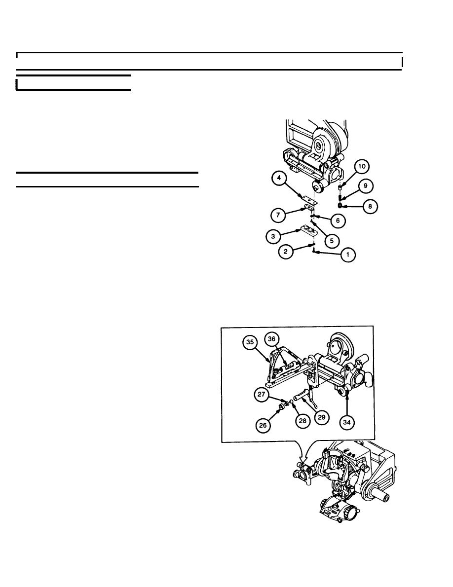
11 Install plate (7), two lug terminals (6), and two ma-
chine screws (5).
12 Install plate insulator (4), plate insulator (3), two
13 Install V-bearing (10), spring (9), and retainer (8)
on M145A1 telescope mount.
d. Adjustment
I
Clamp a 3/8-x 3/4-x 6-inch parallel bar to quad-
1
rant seat of bracket parallel to the quadrant supporl
assembly level (29).
2
Position a zeroed M1A1 gunner's quadrant (35) on
parallel bar, parallel to level (29).
3
Adjust quadrant support assembly level knob (34)
until M1A1 gunner's quadrant (35) level (36) bub-
ble is centered.
4
Loosen threaded ring (26) using fabricated eccen-
tric tool.
5
Apply sealing compound to threaded ring (26) and
install threaded ring (26) in bracket.
6
Engage fabricated eccentric tool into holder (27)
and threaded ring (26).
7
Insert a common straight blade screwdriver
through the center hole in the fabricated eccentric
tool and engage control cam (28).
8
Adjust control cam (28) and holder (27) until the
level (29) bubble is centered within the graduations
on the level (29).
9
Rotate level assembly from 0 to 1330 mils and ad-
just control cam (28) and holder (27) until the level
(29) bubble is centered within the graduations on
the level (29).
10
Rotate level assembly from 1330 roils to 0 and ad-
just control cam (28) and holder (27) until the level
(29) bubble is centered within the graduations on
the level (29).
4-28

