
TM 9-1240-401-34&P
I
4-15. LEVEL ASSEMBLY MAINTENANCE INSTRUCTIONS - continued
J
d. Assembly - continued
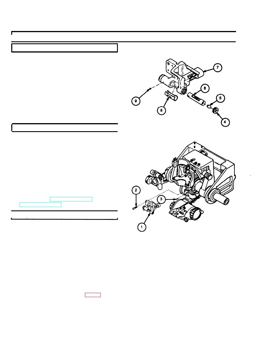
14 If removed, press headless straight pin (9) into
bracket (7) so that the headless straight pin pro-
trudes far enough into the cross-level (6) hole to
engage cross-level (6).
15 Position cover (8) into bracket (7) and slide cross-
Ievel (6) into position so the slot in the end of the
cross-level (6) engages headless straight pin (9).
16 Install cell (5) and secure with threaded ring (4),
using fabricated eccentric tool. Do not tighten
threaded ring (4) at this time.
I
e. Installation
NOTE
Position contact wires in the grooves of the
level assembly. Check to ensure wires are not
pinched between the M145/M145A1 telescope
mount and level assembly during installation.
1 If removed, install two headless straight pins (3).
2 Mount level assembly(1) and secure with two cap
screws (2).
3 Level gun tube (TM 9-2350-31110 or
TM 9-2350-314-10).
f. Adjustment
I
1
Loosen threaded rings (4 and 17) using fabricated
eccentric tool.
2
Place 1/2- by 3/4-by 6-inch parallel baron bear-
ing plate in telescope socket (35) so that it is at
right angle to main shaft (36).
3
Place zeroed M1A1 gunner's quadrant (37) on par-
allel bar.
4
Adjust pitch knob until gunner's quadrant (37) level
(38) bubble is centered.
5
Apply sealing compound (item 15, appx B) to
threaded ring (17) and install threaded ring into
bracket (7).
4-24

