
3-18. LEVEL ASSEMBLY MAINTENANCE INSTRUCTIONS (M118A3) - continued
e. Installation
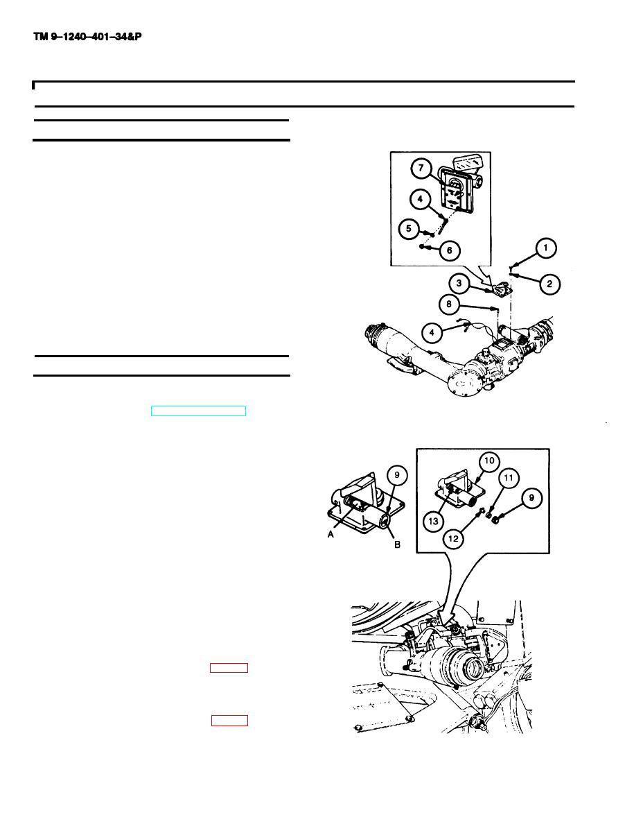
1
If two headless straight pins (8) were removed,
redrill using No. 44 (0.086) drill, drill 3/8 inch (9.53
mm) deep. Ream for drive fit in housing and slip fit
in level assembly (3).
2
Position level assembly (3) over housing and at-
tach wires (4); red wire to positive (+) terminal and
the black wire to the negative (-) terminal of the
circuit board assembly (7) using two new lock-
washers (5) and two nuts (6).
3
Install level assembly (3) over two headless
straight pins (8) and secure with four new lock-
washers (2) and four machine screws (1).
f. Adjustment
1
Install M118A3 elbow telescope on howitzer and
level trunnions (ref. TM 9-2350-311-10).
2
Check that level (13) vial bubble is within the cen-
ter graduation marks of the vial. If bubble is not
within the center graduation marks, go to step 3.
3
Loosen threaded ring (9).
4
Engage fabricated eccentric tool into holder (11)
and threaded ring (9).
5
Insert a straight blade screwdriver through the cen-
ter hole in the eccentric tool.
6
Adjust cam (12) until level (13) vial bubble is cen-
tered.
7
Tighten threaded ring (9), being careful not to dis-
turb setting of vial.
Apply sealing compound (item 15, appx B) in the
8
space (A) between brass portion of level (13) vial
assembly and mount (10).
Apply sealing compound (item 13, appx B) to slot
9
(B) of threaded ring (9) and threads of mount (10).
3-26

