
TM 9-1240-401-34&P
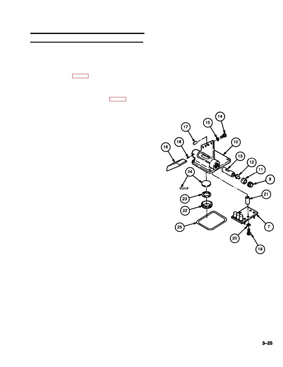
d. Assembly
NOTE
Seal over external side of adapter 10543763
and lamp MS25236-8623 using sealing com-
pound (item 13, appx B) if it has not already
been done. New manufactured level mounts
will not contain an adapter and lamp.
1
Apply sealing compound (item 13, appx B) to the
surface of mount (10) where window (24) is seated.
Install window (24) and apply additional sealing
compound around the window. Install new shim
(23) and using 1-25/32 and 1-51/64 inch tubular
spanner wrench, install retainer (22).
2
If headless straight pin (18) was removed, redrill
using No. 54 (0.055) drill; ream for drive fit in
mount (10). End of headless straight pin (18) must
protrude far enough into hole in mount to engage
slot in end of level (13) when installed.
Install level (13), making sure that slot in end of
3
level engages headless straight pin (18).
Install cam (12), holder (11), and threaded ring (9)
4
in front of level (13). Do not tighten threaded ring
(9) until adjustment of level (13) has been com-
pleted (ref. p 3-26).
Install two sleeve spacers (21), circuit board as-
5
sembly (7), two new lockwashers (20), and two
machine screws (19).
6
If headless straight pins (17) were not removed,
install mirror (16) over headless straight pins (17)
and secure with two new Iockwashers (15) and two
cap screws (14).
7
If headless straight pins (17) were removed, redrill
using No. 54 (0.055) drill; drill 0.450 inch (11.43
mm) deep. Ream for drive fit in mount (10) and slip
fit in mirror (16). Install mirror (16) over headless
straight pins (17) and secure with two new lock-
washers (15) and two cap screws (14).
Apply adhesive to groove on bottom of mount (10)
8
and to one side of new preformed packing (25).
Install preformed packing (25) in groove.

