
TM 9-1240-401-34&P
2-15. M146 TELESCOPE MOUNT FINAL INSPECTION AND ADJUSTMENT - continued
I
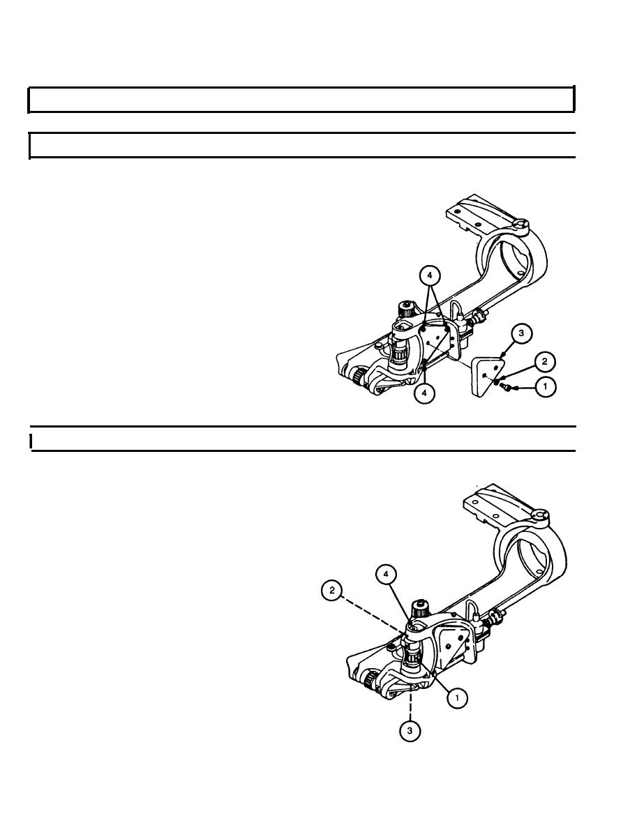
a. CHECKING ELEVATION SLIDE/ELEVATION BRACKET END PLAY
1
Using feeler gage, check that maximum of
0.003-inch (0.008-mm) clearance between ma-
chined surface of elevation slide and elevation
bracket is maintained when the elevation knob is
rotated from stop to stop.
Remove two cap screws (1), two Iockwashers (2),
2
and cover assembly (3). Discard Iockwashers
Tighten or loosen three self-ocking nuts (4) until
3
correct clearance is attained.
Apply sealing compound to three self-locking nuts
4
(4).
5
Install cover assembly (3), two new Iockwashers
(2), and two cap screws (1).
I
b. CHECKING ELEVATION KNOB TRAVEL
1 Rotate elevation knob (1) from stop to stop and
check amount of travel.
NOTE
Elevation knob must rotate 2-1/2 complete
revolutions. If the 2-1/2 revolutions cannot be
met, adjust elevation knob mechanism as di-
rected in steps 2 thru 6.
2
Loosen setscrew (2).
3
Loosen self-locking nut (3).
4
Adjust elevation shoulder screw (4) in or out to ob-
tain minimum travel requirements.
5
Tighten setscrew (2).
6
Tighten self-locking nut (3).
2-22

