
TM 9-1240-382-34
LOCATON
ITEM
REMARKS
ACTION
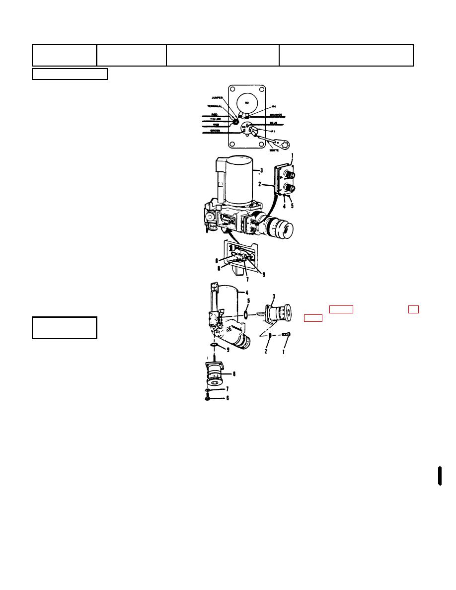
INSTALLATION
Elbow
Switch
Using solder (OS571 (App 8)
Assembly
Assembly,
solder the wires to the switch
Blocking
assembly (1) #*town. Carefully
maneuver a new gasket (2) over
the switch assembly (1) and
position the gasket on the elbow
(3). Position the switch assembly
Switch Assembly (1)
(1 on the elbow (3) and secure
Gasket (2)
the gasket and switch assembly
Elbow Assembly (3)
with lockwashers (4) and screws
Lockwasher (4)
(5). If diode (6) was removed.
Screw (5)
slide insulation sleeving over both
Diode (6)
sections of the red wire from the
Clamp(7)
emergency power connector.
Screw (8)
Solder diode (6) between the two
Terminal Lug (9)
sections of red wire and cover the
soldered
connections
with
sleeving. Position the clamp (7)
over the diode (6) and install the
screw (8) through the clamp (7)
and terminal lugs (9) of the white
ground wires with lugs under the
clamp. Tighten the screw (8).
Fill the two small holes in the
switch cover plate with white
silicone (RTV) adhesive. MIL-A-
REMOVAL
Remove the four screws (1),
Elbow
Boresight
lockwashers (2), and remove the
Assembly
Knobs
deflection
boresight
knob
assembly (3) from the elbow
(4).Remove
the
packing
Screw (1)
(5).Remove the screws (6),
Lockwasher (2)
lockwashers (7), and remove the
Knob Assembly (3)
elevation
boresight
knob
Elbow (4)
assembly (8) from the elbow (4).
Packing (53
Remove the packing (9).
Screw (6)
Lockwasher (7)
Knob Assembly (8)
Packing (9)
All Information on pages 2-16 and 2-1 7, including disassembly, cleaning, inspection/repair, and reassembly procedures,
deleted.
Change 3 2-15

