
C1, TM 9-1240-318-35
Note.
Prior to positioning mount, telescope
M148 or mount, telescope XM164 on top of parallel
(4, fig. 3-1), with dial indicator against surface "a". Move
bar, make certain mating surfaces of mount are
the height gage, along the entire length of surface "A"
clean and free of paint.
and note whether dial of dial indicator has moved.
Surface "A" must be precision leveled; if not, then loosen
c. Position mount, telescope M148 or mount,
the mount elevation locking screw and rotate the "EL"
telescope XM164 on top of parallel bar and against
eccentric -a small amount until surface "A" is leveled.
angle plate. Secure mount to angle plate with a "C"
clamp.
approximately seven inches high and approximately nine
d. Loosen the mount azimuth locking screw. Place
inches in front of the mount. (Use a "V" block, or
screwdriver in the screw slot on the "AZ" worm and turn
equivalent holding device, to mount projector collimator.)
from stop-to-stop.
Note how much the worm has
Set the projector collimator to 1000 meters by rotating
traveled. Position worm in the center of its mechanical
the knurl knob.
travel. Lock in position by tightening the azimuth locking
screw.
e. Loosen the mount elevation locking screw.
Place screwdriver in the eccentric "EL" screw slot and
turn from stop-to-stop. Note how much the screw has
i. Plumb the collimating telescope to a plumb line
traveled.
Position the screw in the center of its
and lock in position.
mechanical travel. Lock in position by tightening the
elevation locking screw.
j. Place the collimating telescope in front of the
projector collimator.
Sight through the collimating
telescope and rotate the projector
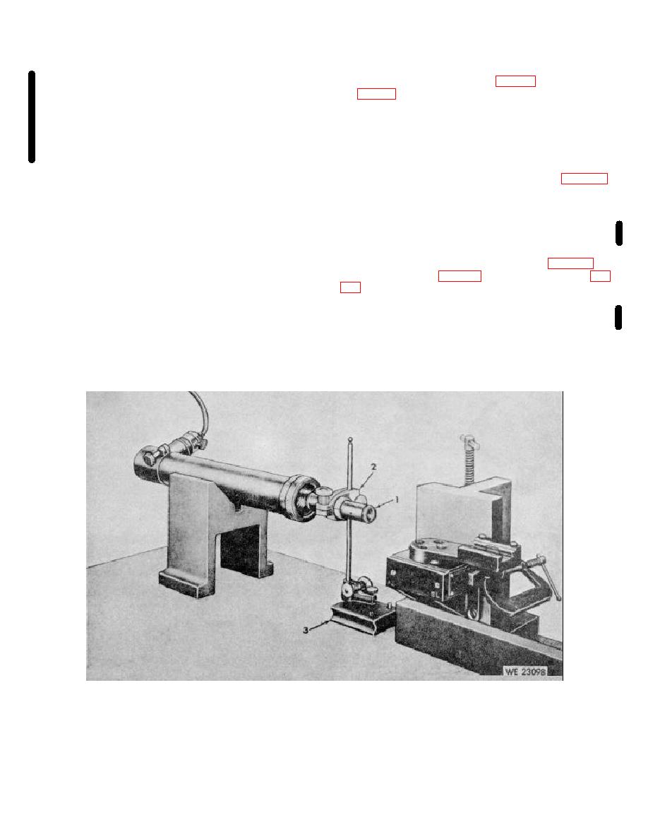
1
Collimating telescope 4931-554-9180
2
Telescope holder 4931-612-1110
3
Surface gage 5210-221-1842
Figure 3-2. Setup of testing fixture.
3-3

